Heating pad

a heating pad and electric heating technology, applied in the field of improved electric heating pads, can solve the problems of skin burns from electric heating pads, skin burns, etc., and achieve the effect of preventing burns and preventing burns

Active Publication Date: 2016-11-29
TRIODYNE SAFETY SYST L L C
View PDF6 Cites 0 Cited by
  • Summary
  • Abstract
  • Description
  • Claims
  • Application Information

AI Technical Summary

Benefits of technology

[0016]A general object of the invention is to provide an improved electric heating pad which can eliminate or reduce the incident of burns due to both sides of the electric heating pad being covered during use.
[0018]The heating pad device of this invention seeks to prevent skin burns due to covering both sides of a heating pad by: monitoring an absolute temperature of each surface of the heating pad; monitoring a temperature difference between each surface of the heating pad, where a small temperature difference indicates that both sides of the heating pad are covered; and by monitoring the duty cycle of the heating element, where, when at steady state operation, a large off portion of the duty cycle indicates both sides of the heating pad are covered.
[0023]In a preferred embodiment, the heating pad of this invention further includes a permanently attached cover to prevent burns due to users using the heating pad without a cover and a switch, such as a dead-man switch and a timed switch, to prevent burns due to users falling asleep during use.

Problems solved by technology

Many incidents of skin burns from electric heating pads are due to consumers improperly using the heating pad by placing a cover over the heating pad and positioning the heating pad between the body and a furniture piece.
Both of these improper uses confine all or most of the heat energy generated by heating elements to an area of application on the body increasing the quantity and rate of heat transfer into the body.
Covering both sides of the heating pad, one by the body and the opposite by a cover or furniture, can result in nearly all of heat energy generated by the heating pad to be transferred to the skin of the user which may result in skin burns.

Method used


Image

  • Heating pad
  • Heating pad
  • Heating pad

Examples


Embodiment Construction

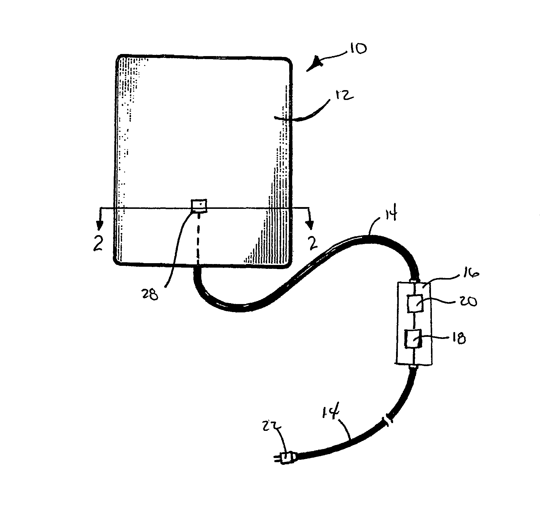
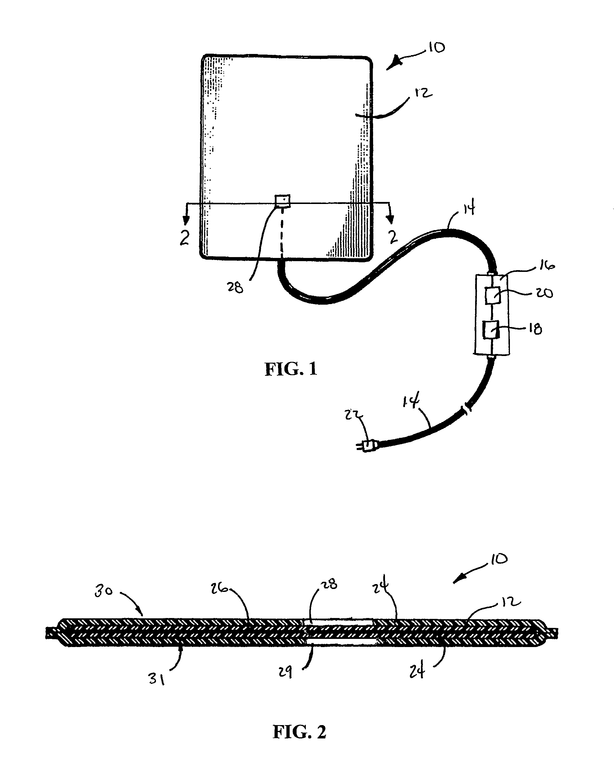
[0028]FIGS. 1 and 2 show a preferred embodiment of an electric heating pad 10 of this invention which can eliminate or reduce skins burns by detecting when both sides of the electric heating pad are covered and shutting off the device.

[0029]The electric heating pad 10 of this invention seeks to prevent skin burns by: monitoring an absolute temperature of each surface of the heating pad 10; monitoring a temperature difference between each surface of the heating pad 10, where a small temperature difference indicates that both sides of the heating pad 10 are covered; and by monitoring a duty cycle of the heating pad 10, where a large off portion of the duty cycle indicates both sides of the heating pad 10 are covered.

[0030]As shown in FIGS. 1 and 2, the electric heating pad 10 according to an embodiment of this invention comprises a pad 12, a cord 14, a control box 16 including an on / off switch 18 and a processor 20, and a plug 22. The processor 20 preferably comprises a programmable l...


PUM


Abstract

An improved heating pad which minimizes or eliminates skin burns due to improper uses in three ways: by monitoring an absolute temperature of each surface of the heating pad; by monitoring a temperature difference between each surface of the heating pad, where a small temperature difference indicates that both sides of the heating pad are covered; and by monitoring the duty cycle of a heating element, where a large off portion of the duty cycle indicates both sides of the heating pad are covered.

Description

CROSS REFERENCE TO RELATED APPLICATION[0001]This application claims priority to U.S. Provisional Patent Application 61 / 694,642, filed 29 Aug. 2012, and entitled “Safety Controls To Assure One Uncovered Heating Pad Face.” This priority application is hereby incorporated by reference herein and made a part hereof, including but not limited to those portions which specifically appear hereinafter.BACKGROUND OF THE INVENTION[0002]Field of the Invention[0003]This invention is directed to an improved electric heating pad which prevents burns resulting from improper use. More specifically, this invention is directed to an improved electric heating pad which monitors temperatures of surfaces of the heating pad and / or monitors a duty cycle of an internal thermostat to detect when the heating pad is covered.[0004]Discussion of Related Art[0005]Electric heating pads are used by many for pain relief and to improve local blood circulation. However, use of electric heating pads is also associated ...

Claims


Application Information

Patent Timeline
Patent Type & Authority Patents(United States)
IPC IPC(8): A61F7/08A61F7/00A61F7/02
CPCA61F7/08A61F7/007A61F2007/0071A61F2007/0086A61F2007/0093A61F2007/0095A61F2007/0296
Inventor BARNETT, RALPH LIPSEYWINGFIELD, JAMES R.
Owner TRIODYNE SAFETY SYST L L C
Why Eureka
Try Eureka