Check patentability & draft patents in minutes with Patsnap Eureka AI!

Heat sink with orientable fins

a technology of heat sinks and fins, which is applied in the direction of instruments, semiconductor/solid-state device details, and electrical apparatus casings/cabinets/drawers, etc., can solve the problems of dramatic loss of heat sink efficiency, and failure of one or more air movers to change the direction of air flow

Active Publication Date: 2016-11-29
LENOVO ENTERPRISE SOLUTIONS (SINGAPORE) PTE LTD
View PDF87 Cites 8 Cited by
  • Summary
  • Abstract
  • Description
  • Claims
  • Application Information

AI Technical Summary

Problems solved by technology

For example, if a computer chassis or server rack has multiple air movers disposed in a row or array, the failure of one or more air movers will change the direction of air flow across heat sink fins disposed within the computer chassis or server rack.
As a result, the efficiency of the heat sink will decrease due to the misalignment of the air flow across the fins of the heat sink.
As another example, obstructions such as expansion cards, circuit boards or even articles inadvertently placed near an air inlet or outlet of the chassis or rack can disrupt and change the direction of air flow across a heat sink, thereby resulting in a dramatic loss of heat sink efficiency due to misaligned air flow across the fins.

Method used


Image

  • Heat sink with orientable fins
  • Heat sink with orientable fins
  • Heat sink with orientable fins

Examples


Embodiment Construction

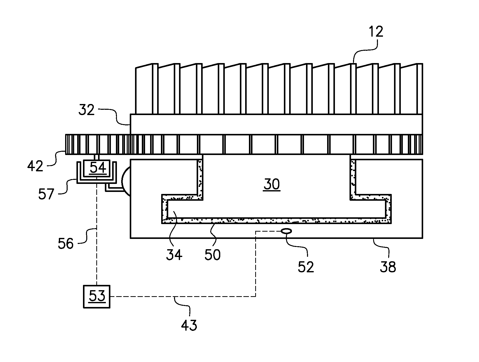
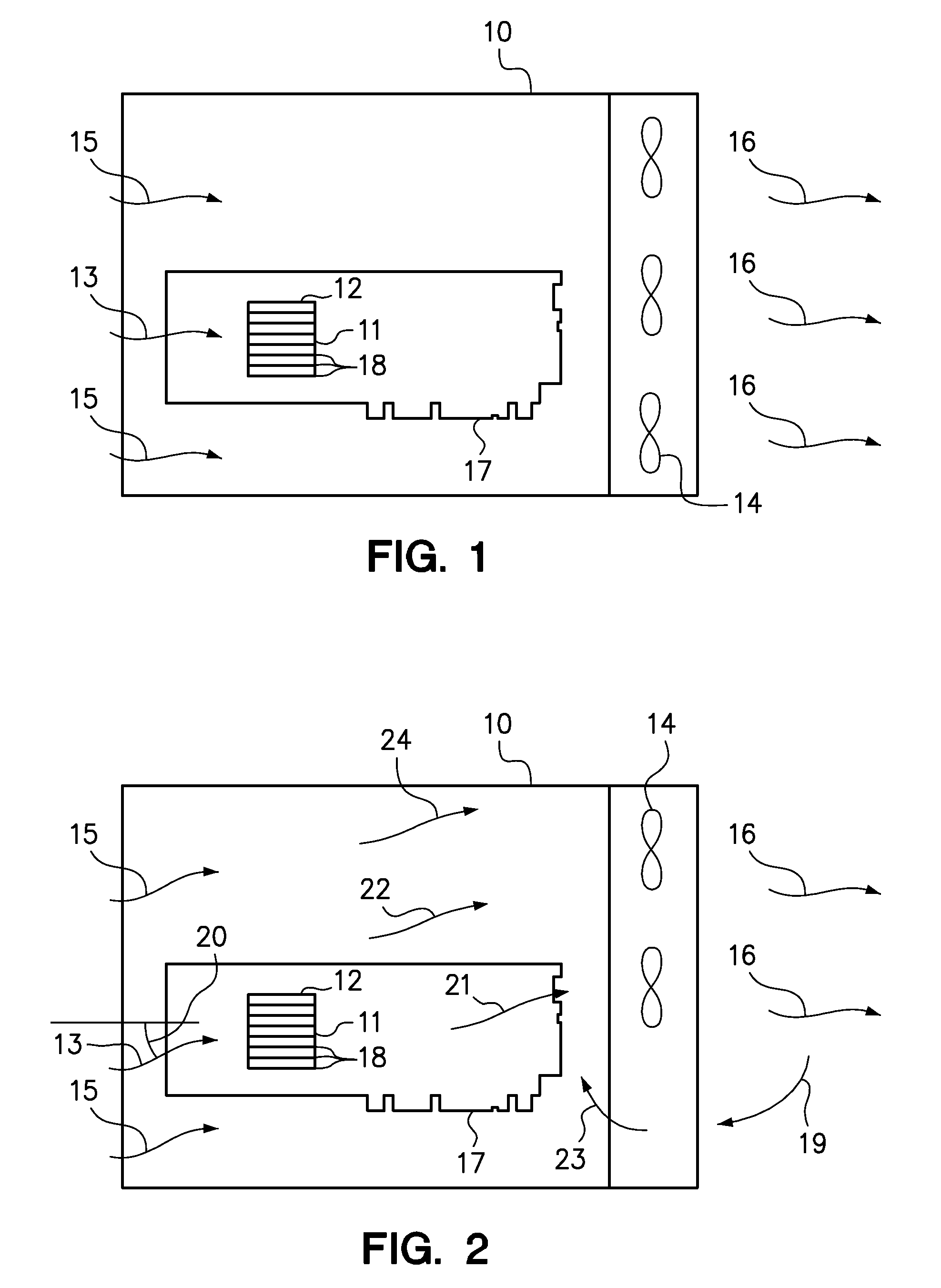
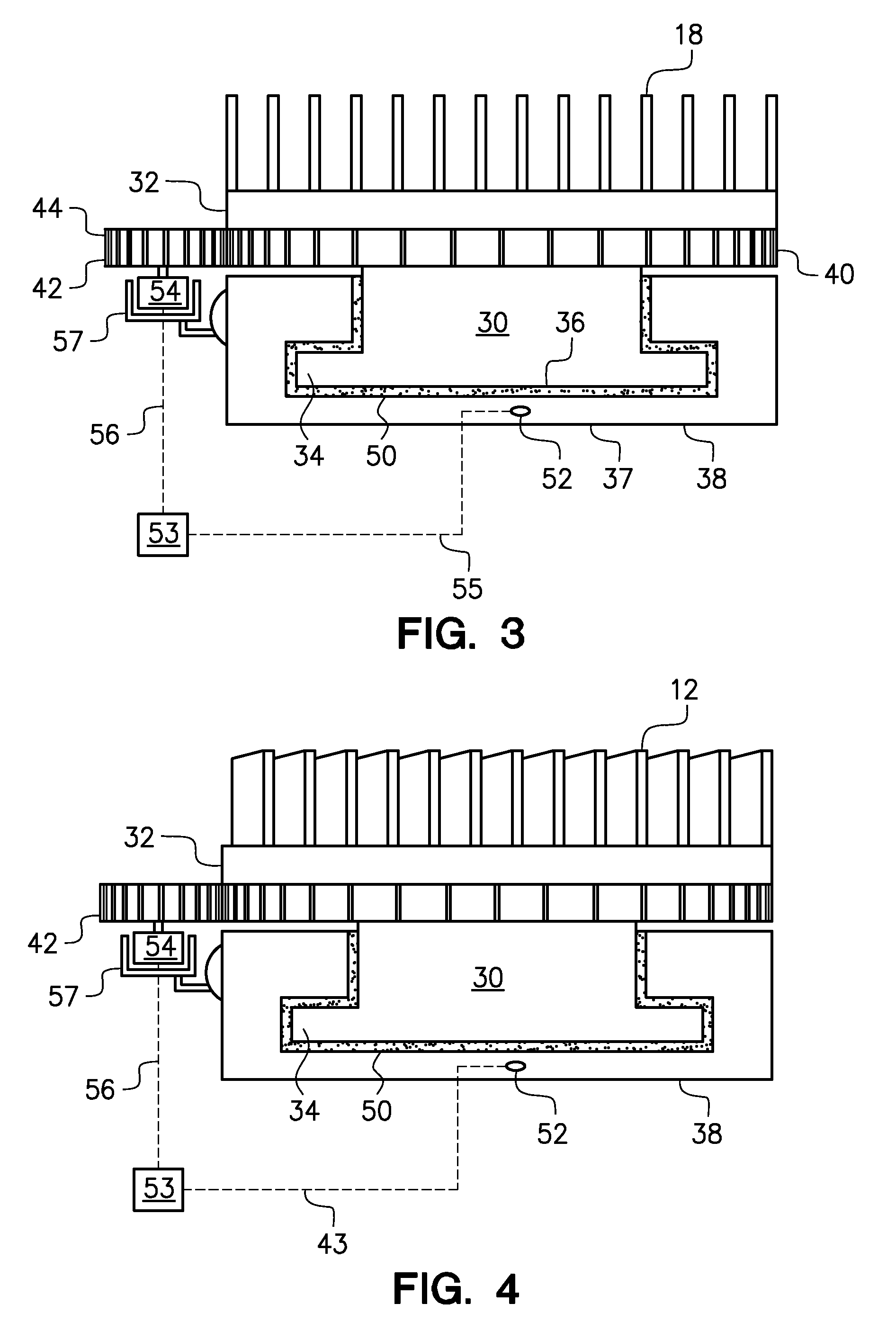
[0014]One embodiment of the present invention provides a heat sink having a drive member, a base and a rotary member to support a plurality of air-cooled fins. The rotary member is rotatably disposed on the base adapted to engage a heat-generating electronic device, such as a processor, disposed within a computer chassis. The drive member may be activated to rotate the rotary member to align the fins with an air flow within the computer chassis to remove heat generated by the processor by way of dissipation from the fins.

[0015]Embodiments of the heat sink may further comprise a temperature sensor coupled to at least one of the base and the rotary member to generate a signal corresponding to the temperature of the base or the rotary member. The temperature signal is communicated to a controller that activates the drive member to rotate the rotary member and thereby align the fins on the rotary member with an air flow within the chassis.

[0016]Alternate embodiments of the heat sink com...


PUM


Abstract

A heat sink comprises a plurality of fins that may be positioned in a plurality of orientations relative to a heat-generating electronic component to which the heat sink is thermally coupled. A controller may be used to detect an elevated processor temperature and to activate a drive member to automatically adjust the orientation of fins on the heat sink. The fins may be moved and aligned with an air flow made over the heat sink. The adjustable-fin heat sink affords added flexibility in arranging a processor or other heat-generating electronic component on a circuit board. The orientation or position of the heat sink fins may also be automatically changed in response to a change in the air flow direction as manifested by a rise in the temperature of the heat sink or the heat-generating member.

Description

BACKGROUND[0001]Field of the Invention[0002]The present invention relates to heat sinks for removing heat from heat-generating electronic components used in computers.[0003]Background of the Related Art[0004]Computer systems require removal of heat from heat-generating electronic components such as processors. Heat-generating electronic components are generally coupled to a generally planar host card such as a circuit board having a series of electronic contacts along an edge to facilitate electronic engagement between the host card and a motherboard. Electrical current and data are routed to the heat-generating electronic component through the motherboard and through the electronic contacts on the circuit board. Heat generated by the electronic component may be transferred by conduction to a heat sink. A plurality of fins may be coupled to the heat sink to dissipate heat to surrounding air within the computer chassis. Air flow within the chassis may be provided by air movers such a...

Claims


Application Information

Patent Timeline
Patent Type & Authority Patents(United States)
IPC IPC(8): G06F1/20H01L23/467H01L23/34
CPCG06F1/20H01L23/34H01L23/467H01L2924/0002H01L2924/00F28F7/00F28F13/00
Inventor BUSCH, DIANE S.JUNE, MICHAEL S.NI, CHUNJIANRAMINENI, PRADEEP
Owner LENOVO ENTERPRISE SOLUTIONS (SINGAPORE) PTE LTD
Features
  • R&D
  • Intellectual Property
  • Life Sciences
  • Materials
  • Tech Scout
  • Unparalleled Data Quality
  • Higher Quality Content
  • 60% Fewer Hallucinations
Learn More