Check patentability & draft patents in minutes with Patsnap Eureka AI!

Oil detection device, compressor having the same and method of controlling the compressor

a technology of oil detection device and compressor, which is applied in the direction of positive displacement liquid engine, piston pump, instruments, etc., can solve the problems of increasing the length of the pipe in which oil and working fluid flow is increased, the method is not economically efficient, and the difficulty in controlling the oil level of the compressor,

Active Publication Date: 2016-12-13
SAMSUNG ELECTRONICS CO LTD
View PDF35 Cites 2 Cited by
  • Summary
  • Abstract
  • Description
  • Claims
  • Application Information

AI Technical Summary

Benefits of technology

The oil detection device enhances the accuracy of oil level monitoring, reduces unnecessary oil collection, and improves compressor efficiency by providing real-time feedback for optimal oil management.

Problems solved by technology

In this case, the compression and electrical assemblies share a rotating shaft, the rotating shaft is rotated based on power generated by the electric assembly and the compression assembly coupled to the rotating shaft is operated through such rotation, thus causing compression.
However, as configurations of the compressor gradually become more complicated and compressors are used for large air conditioners, multi-air conditioning systems and the like, pipes in which oil and working fluids flow are increased in length and control of oil levels in the compressors thus gradually become more difficult.
Such an oil level is commonly checked by the naked eye through a transparent window formed in the compressor casing, but this method is not economically efficient and an oil collection operation is thus actually performed on a cycle of a predetermined time, regardless of oil levels.
However, in this case, in actuality, the oil collection operation may be compulsively performed although an oil level is sufficient.
For this reason, for example, air conditioners inefficiently consume energy while not providing cooling.
The oil level sensor as described above may have the effects of reducing unnecessary oil collection operation, thus decreasing energy consumption and increasing compressor operation time according to intended application.
However, a calculation operation for converting a physical property value into an oil level is involved, thus disadvantageously making an overall configuration complicated and increasing cost, because a physical property value changed according to contact with oil is read, an oil level corresponding to the measured physical property value is calculated and an actual oil level is checked, the actual oil level is compared with a preset level and whether or not oil collection operation is performed is determined.

Method used


Image

  • Oil detection device, compressor having the same and method of controlling the compressor
  • Oil detection device, compressor having the same and method of controlling the compressor
  • Oil detection device, compressor having the same and method of controlling the compressor

Examples


Embodiment Construction

[0078]Reference will now be made in detail to the embodiments of the present disclosure, examples of which are illustrated in the accompanying drawings, wherein like reference numerals refer to like elements throughout.

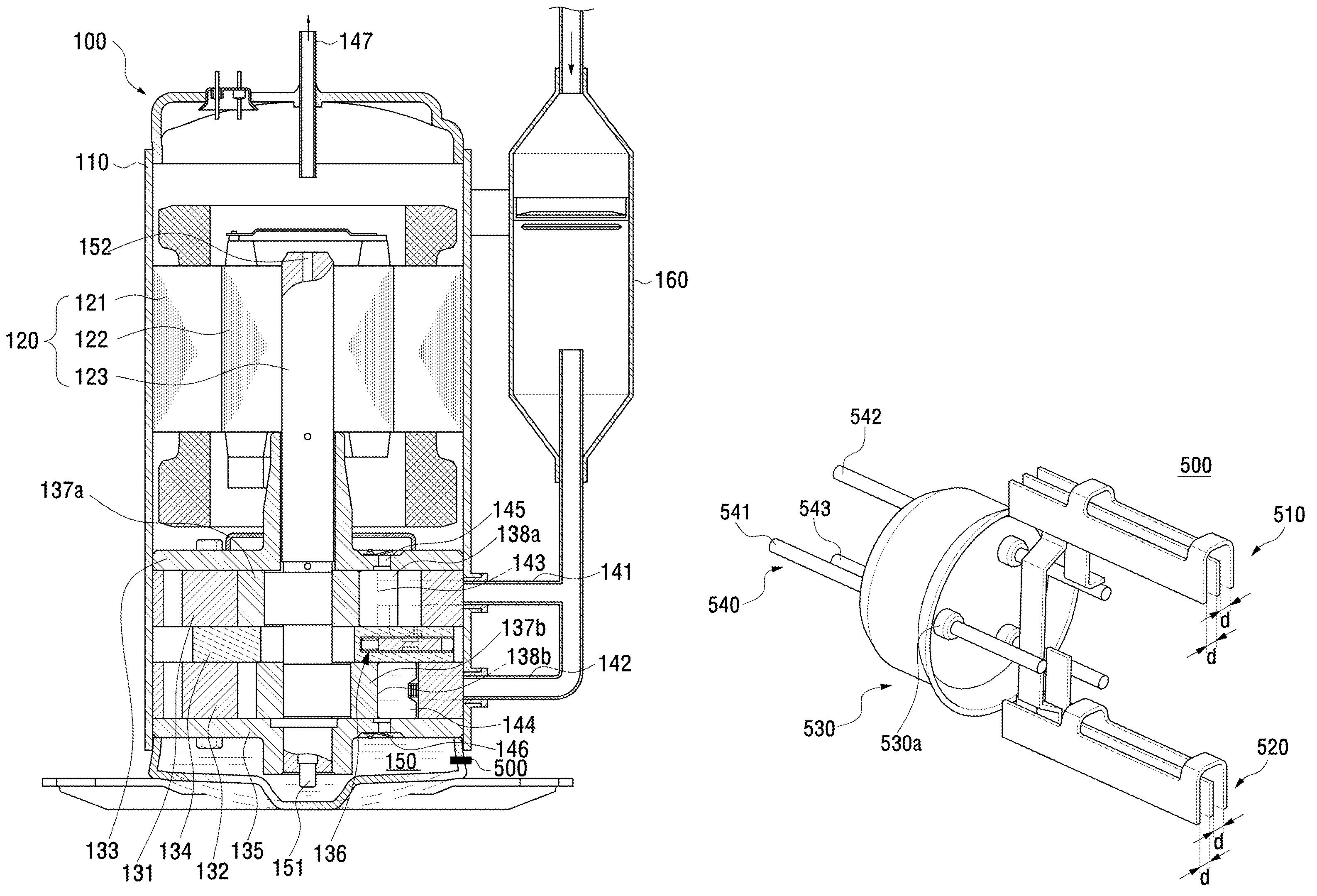
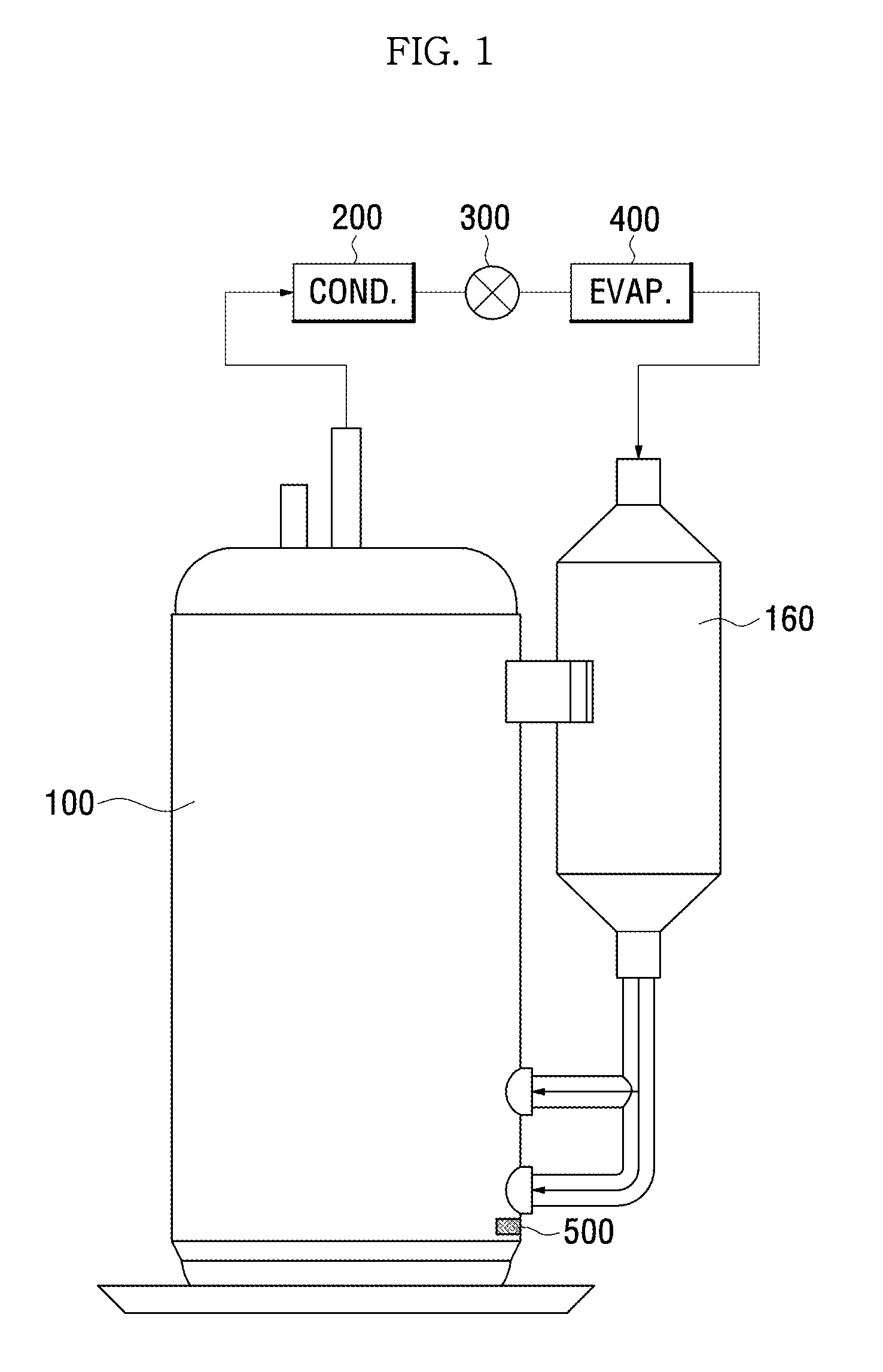
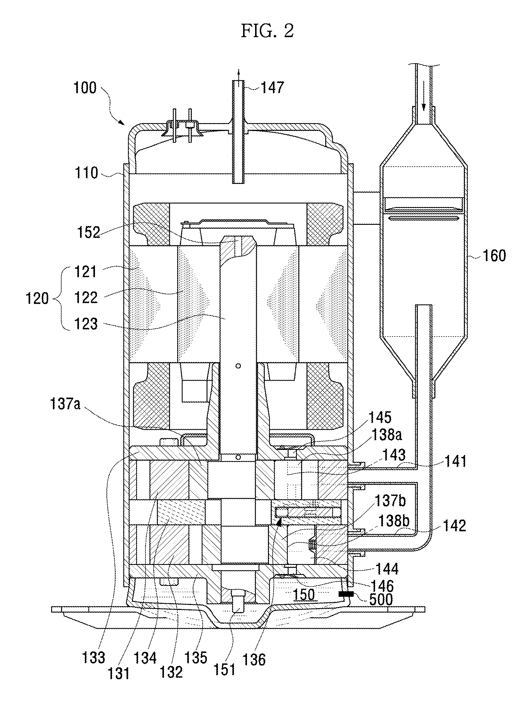
[0079]FIG. 1 is a view illustrating an example of a refrigeration cycle having a compressor according to an embodiment.

[0080]The refrigeration cycle includes a compressor 100, a first heat exchanger 200, an expansion valve 300 and a second heat exchanger 400.

[0081]The compressor 100 compresses a refrigerant and discharges the compressed refrigerant as a high-temperature high-pressure gas to the first heat exchanger 200.

[0082]The first heat exchanger 200 is connected to a discharge outlet of the compressor 100 through a refrigerant pipe and condenses the refrigerant supplied from the compressor 100 through heat emission of the refrigerant. In this case, the high-temperature high-pressure gas refrigerant is phase-changed into a high-temperature high-pressure liquid refr...


PUM


Abstract

An oil detection device for a compressor to detect at least two levels of oil in the compressor includes a first detection unit including a first reference electrode and a first detection electrode disposed at both sides of the first reference electrode, and a second detection unit including a second reference electrode spaced from the first reference electrode and a second detection electrode disposed at both sides of the second reference electrode.

Description

CROSS-REFERENCE TO RELATED APPLICATIONS[0001]This application claims the benefit of Korean Patent Application No. 10-2013-0158482, filed on Dec. 18, 2013 in the Korean Intellectual Property Office, the disclosure of which is incorporated herein by reference.BACKGROUND[0002]1. Field[0003]Embodiments of the present disclosure relate to an oil detection device to detect a level of oil in a compressor, a compressor having the same and a method of controlling the compressor.[0004]2. Description of the Related Art[0005]A compressor has a structure in which a compression assembly to aspirate and compress a refrigerant is disposed in a lower part of a casing and an electric assembly is disposed in an upper part of the compression assembly.[0006]In this case, the compression and electrical assemblies share a rotating shaft, the rotating shaft is rotated based on power generated by the electric assembly and the compression assembly coupled to the rotating shaft is operated through such rotati...

Claims


Application Information

Patent Timeline
Patent Type & Authority Patents(United States)
IPC IPC(8): G01F23/26
CPCG01F23/265G01F23/266G01F23/268F04B39/0207F04B35/04G01F23/26F04C28/00F04C29/02
Inventor LEE, HYO SANGKIM, BYUNG GUHAN, JEONG SU
Owner SAMSUNG ELECTRONICS CO LTD
Features
  • R&D
  • Intellectual Property
  • Life Sciences
  • Materials
  • Tech Scout
  • Unparalleled Data Quality
  • Higher Quality Content
  • 60% Fewer Hallucinations
Learn More