
Spacer element

a spacer element and element technology, applied in the field of spacer elements, can solve problems such as difficulty or inability to easily access the head

Active Publication Date: 2016-12-20
NEOSS LTD
View PDF23 Cites 9 Cited by
  • Summary
  • Abstract
  • Description
  • Claims
  • Application Information

AI Technical Summary

Problems solved by technology

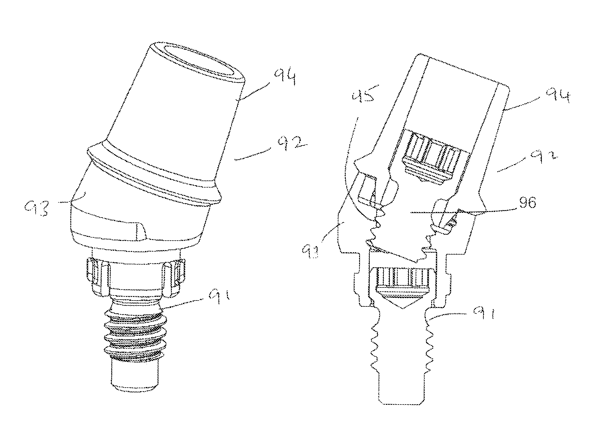
However, the provision of an inclined abutment (angulated relative to the implant screw and thereby the implant) is problematical since it makes it difficult or impossible to easily access the head of the implant screw with the usual (substantially straight) tool through the angulated abutment bore.

Method used


Image

  • Spacer element
  • Spacer element
  • Spacer element

Examples


Embodiment Construction

[0037]Throughout the description and claims of this specification, the words “comprise” and “contain” and variations of the words, for example, “comprising” and “comprises,” means “including but not limited to,” and is not intended to (and does not) exclude other components, integers or steps.

[0038]Throughout the description and claims of this specification, the singular encompasses the plural unless the context otherwise requires. In particular, where the indefinite article is used, the specification is to be understood as contemplating plurality as well as singularity, unless the context requires otherwise.

[0039]Features, integers, characteristics, compounds or groups described in conjunction with a particular aspect, embodiment or example of the invention are to be understood to be applicable to any other aspect, embodiment or example described herein unless incompatible therewith.

[0040]Throughout the description and claims of this specification, the terms “aperture” and “bore” i...


PUM


Abstract

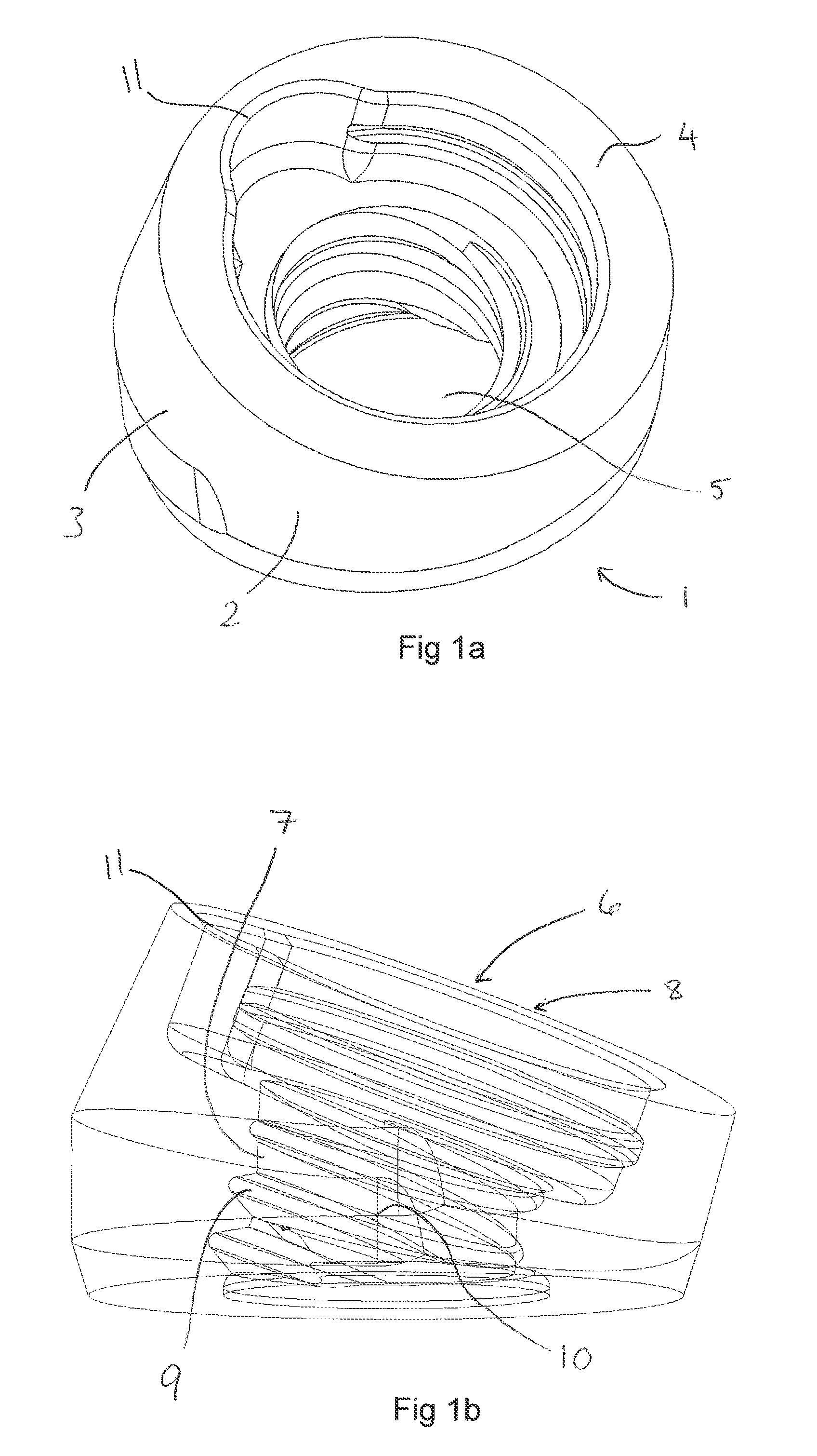
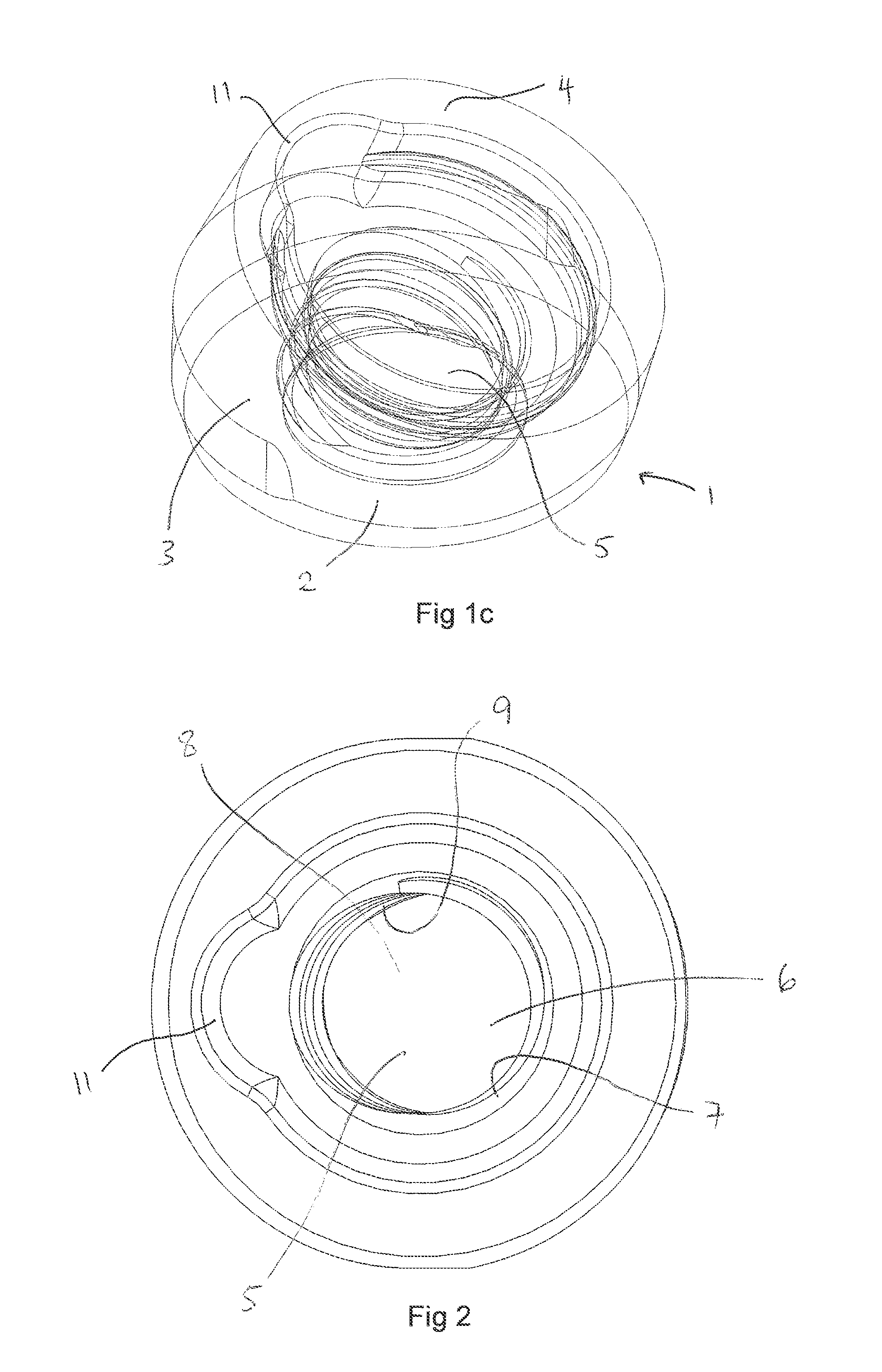
Various embodiments for a spacer element that may be used in a dental implant assembly are described. In one example, the spacer element has a single aperture therethrough. Further, the single aperture includes an implant screw access bore and an offset abutment screw bore, longitudinal axes of which intersect within the single aperture.

Description

FIELD OF THE INVENTION[0001]The present invention relates to the field of a novel spacer element for use in connection with a dental implant assembly and particularly a spacer element for use with an angulated or inclined abutment.[0002]The present invention also relates to the field of a dental implant assembly comprising such a novel spacer element and to an implant screw pre-mounted in such a spacer element. Furthermore the invention relates to the field of a novel dental construction e.g., a dental bridge comprising one or more spacer elements and to methods related thereto.BACKGROUND[0003]In a dental implant assembly, there is usually a fixing of some kind for fixing, inter alia, an abutment or a spacer element to a dental implant. Typically, the fixing is a screw known as an implant screw. This implant screw is not the same as the implant per se which is itself externally threaded.[0004]It is often desirable to have the abutment positioned at an inclined angle relative to (i.e...

Claims


Application Information

Patent Timeline
Patent Type & Authority Patents(United States)
IPC IPC(8): A61C8/00
CPCA61C8/005A61C8/0068
Inventor ENGMAN, FREDRIK NILS
Owner NEOSS LTD
Learn More