

Wind instrument supports
a technology for wind instruments and supports, applied in the field of instruments, can solve problems such as discomfort, strain, and overuse injuries
- Summary
- Abstract
- Description
- Claims
- Application Information
AI Technical Summary
Benefits of technology
Problems solved by technology
Method used
Image

Examples
first embodiment
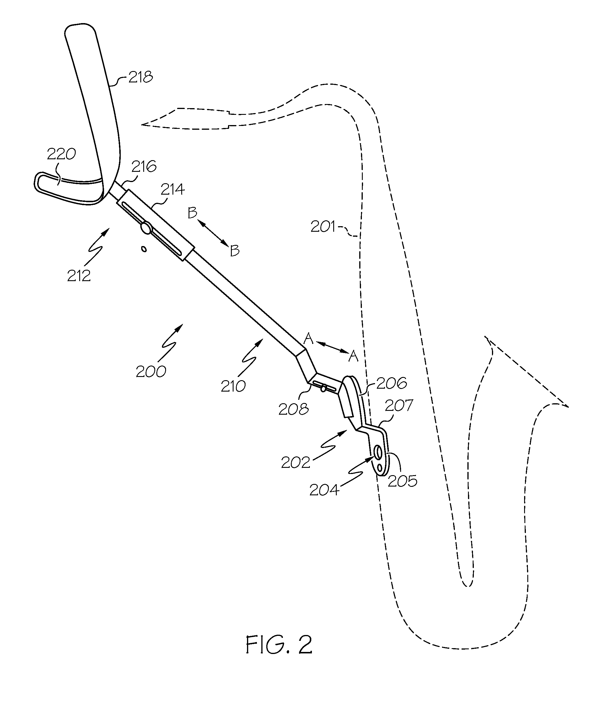
[0011]With reference again to the figures and with particular reference to FIG. 2, an instrument support 200 for a wind musical instrument 201 in accordance with the present invention is illustrated.
[0012]Instrument support 200 includes a bracket 202 that is configured to be attached to wind instrument 201, for example, by a fastener (e.g., screw) installed through one or more holes 204 that correspond to one or more recesses in the body of wind instrument 201. For brass woodwind instruments, such as saxophones, it is common for a single screw to be used and for the corresponding recess to be threaded. For wood-bodied woodwind instruments, such as clarinets, oboes and English horns, additional recesses may be employed. In at least some implementations, bracket 202 attaches to wind instrument 201 in place of the conventional thumb rest using the recess(es) provided to attach the conventional thumb rest. As described below, replacement of the conventional thumb rest with instrument su...
second embodiment
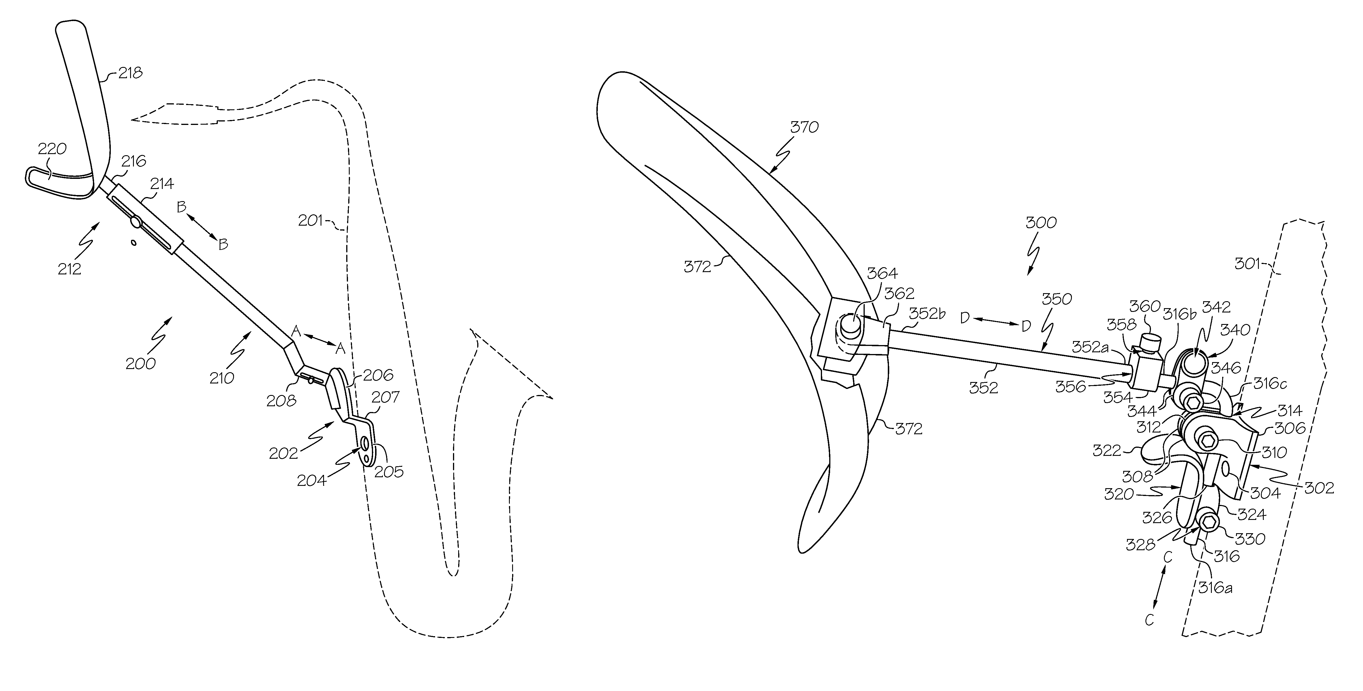
[0019]With reference now to FIG. 3, an instrument support 300 according to the present invention is illustrated. Instrument support 300 can advantageously be utilized to support a wood-bodied woodwind instrument 301, such as clarinet, oboe, or English horn.
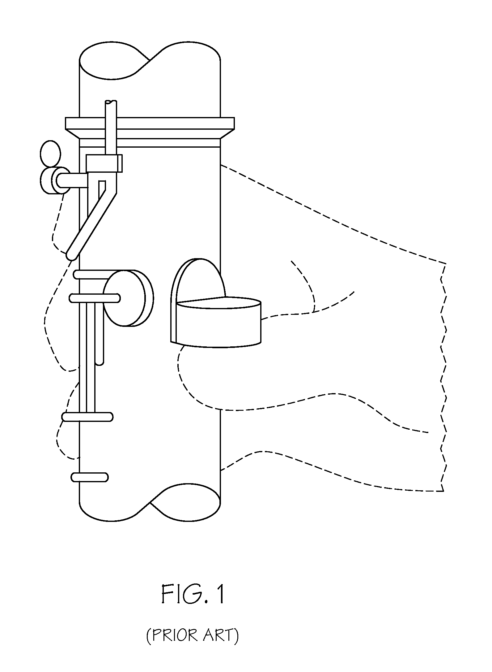
[0020]Instrument support 300 includes a bracket 302 configured to attach to woodwind instrument 301, a base section 370 configured to rest on the trunk of a user, and one or more support members (e.g., rod 316 and shaft 350) spanning a distance between bracket 302 and base section 370. In the illustrated embodiment, bracket 302 can be attached to woodwind instrument 301 by fasteners (e.g., screw(s)) installed through one or more holes 304 that correspond to one or more recesses in the body of instrument 301. In at least some implementations, bracket 302 attaches to woodwind instrument 301 in place of the conventional thumb rest supplied with woodwind instrument 301 (see, e.g., FIG. 1) using the recess(es) in woodwind instrument 30...
third embodiment
[0029]Referring now to FIG. 4, an instrument support 400 according to the present invention is illustrated. Instrument support 400 can advantageously be utilized to support a brass woodwind instrument 301, such as a soprano, tenor, alto or baritone saxophone.
[0030]Instrument support 400 includes a bracket 402 configured to attach to woodwind instrument 401, a base section 470 configured to rest on the trunk of a user, and one or more support members (e.g., rod 416 and shaft 450) spanning a distance between the bracket and the base section. In the illustrated embodiment, bracket 402 can be attached to woodwind instrument 401 by one or more fasteners (e.g., screw(s)) installed through one or more holes 404 that correspond to one or more recesses in the body of instrument 401. In at least some implementations, bracket 402 attaches to the instrument in place of the conventional thumb rest supplied with woodwind instrument 401 using the threaded recess(es) in woodwind instrument 401 prov...
PUM
 Abstract
Description
Claims
Application Information