
Intravenous catheter protective cover

a protective cover and catheter technology, applied in the field of intravenous catheters, can solve the problems of loss of unsecured catheters, difficulty in applying sticky tape to the skin while wearing gloves, and complicated process of securing catheters, so as to avoid premature adhesion to the skin surface, maintain hygienic precautions

Active Publication Date: 2016-12-27
BENNETT TIONNE ALLEN
View PDF12 Cites 1 Cited by
  • Summary
  • Abstract
  • Description
  • Claims
  • Application Information

AI Technical Summary

Benefits of technology

Facilitates easy, hygienic securement of catheters near the puncture site, preventing accidental dislodgement and maintaining protection for medical personnel by ensuring the catheter remains in place without exposing adhesive until necessary.

Problems solved by technology

Using precautions, such as sterile gloves, while inserting the catheters has made the process of securing these catheters complicated.
Indeed, in general, it is difficult to apply sticky tape to the skin while wearing gloves.
In addition, the extra movement needed to reach for and to apply such tape risks the loss of the unsecured catheter.
A difficulty encountered with such prior art products, however, is that the protective covering for the adhesive on the wings must be removed before the needle is inserted into the vein so that it may be thereafter adhered to the skin surface.
Providing an adhesive surface that is exposed before vein puncture, however, risks premature adhesion to the skin and / or adhesion to the medial care provider's gloves.
However, once the catheter is secured at the site of insertion, there is no cover or protective structure that will prevent the accidental dislodgement of the catheter from the patient's skin.

Method used


Image

  • Intravenous catheter protective cover
  • Intravenous catheter protective cover
  • Intravenous catheter protective cover

Examples


Embodiment Construction

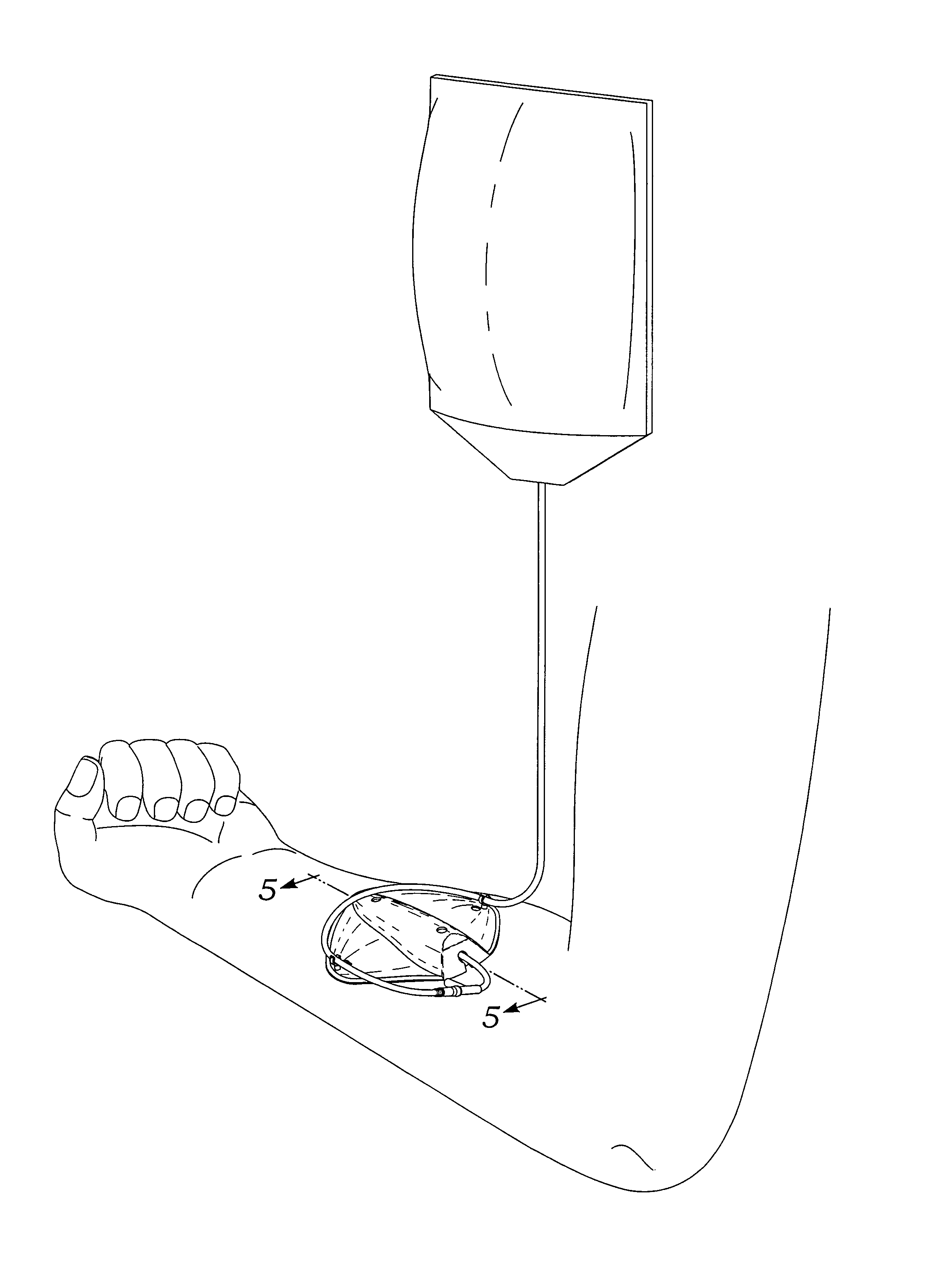
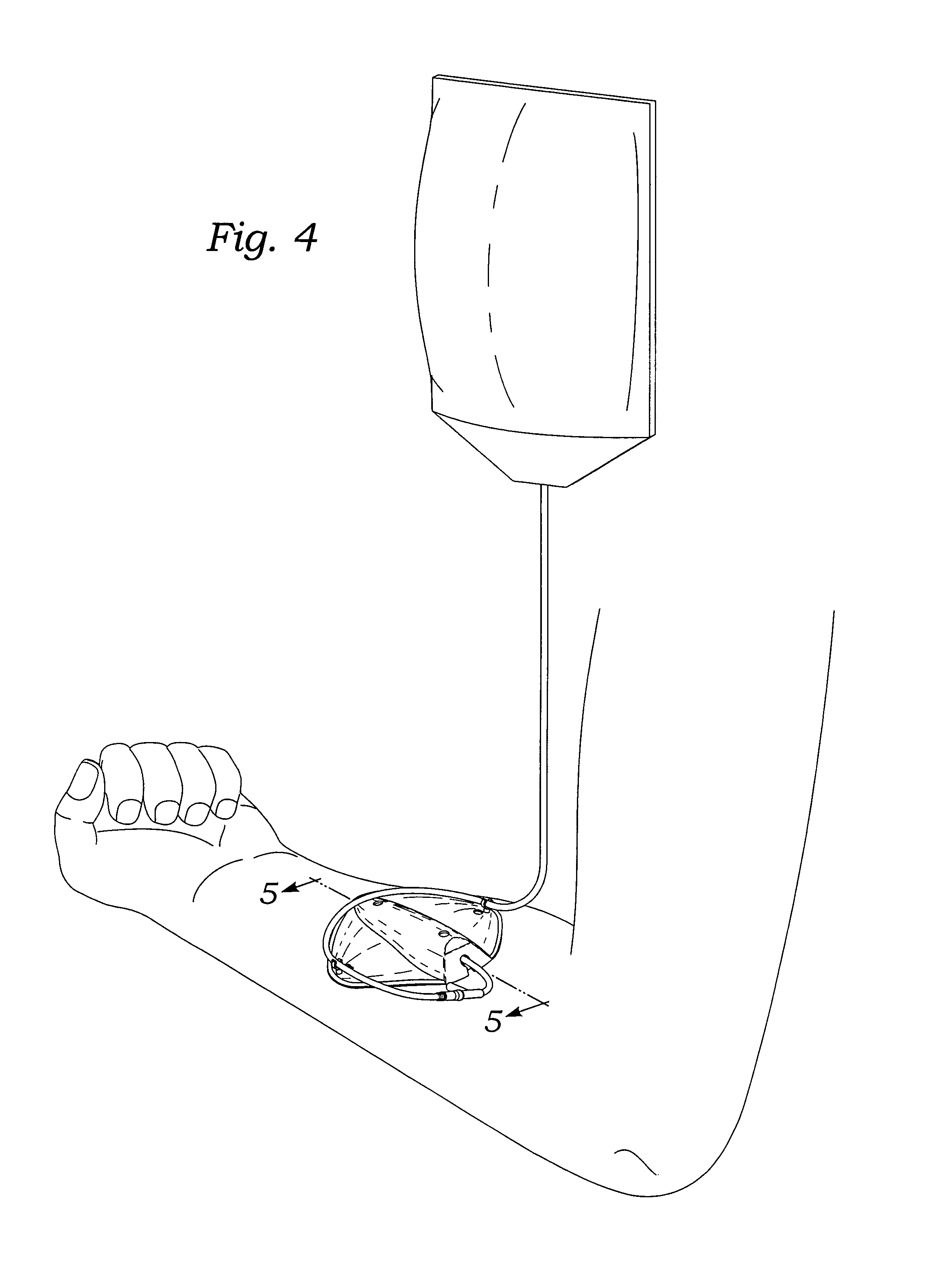
[0024]The following description is provided to enable any person skilled in the art to make and use the invention and sets forth the best modes contemplated by the inventor of carrying out his invention. Various modifications, however, will remain readily apparent to those skilled in the art, since the generic principles of the present invention have been defined herein specifically to provide a novel construction and method for securing a catheter at the site of insertion of the catheter needle into a patient.

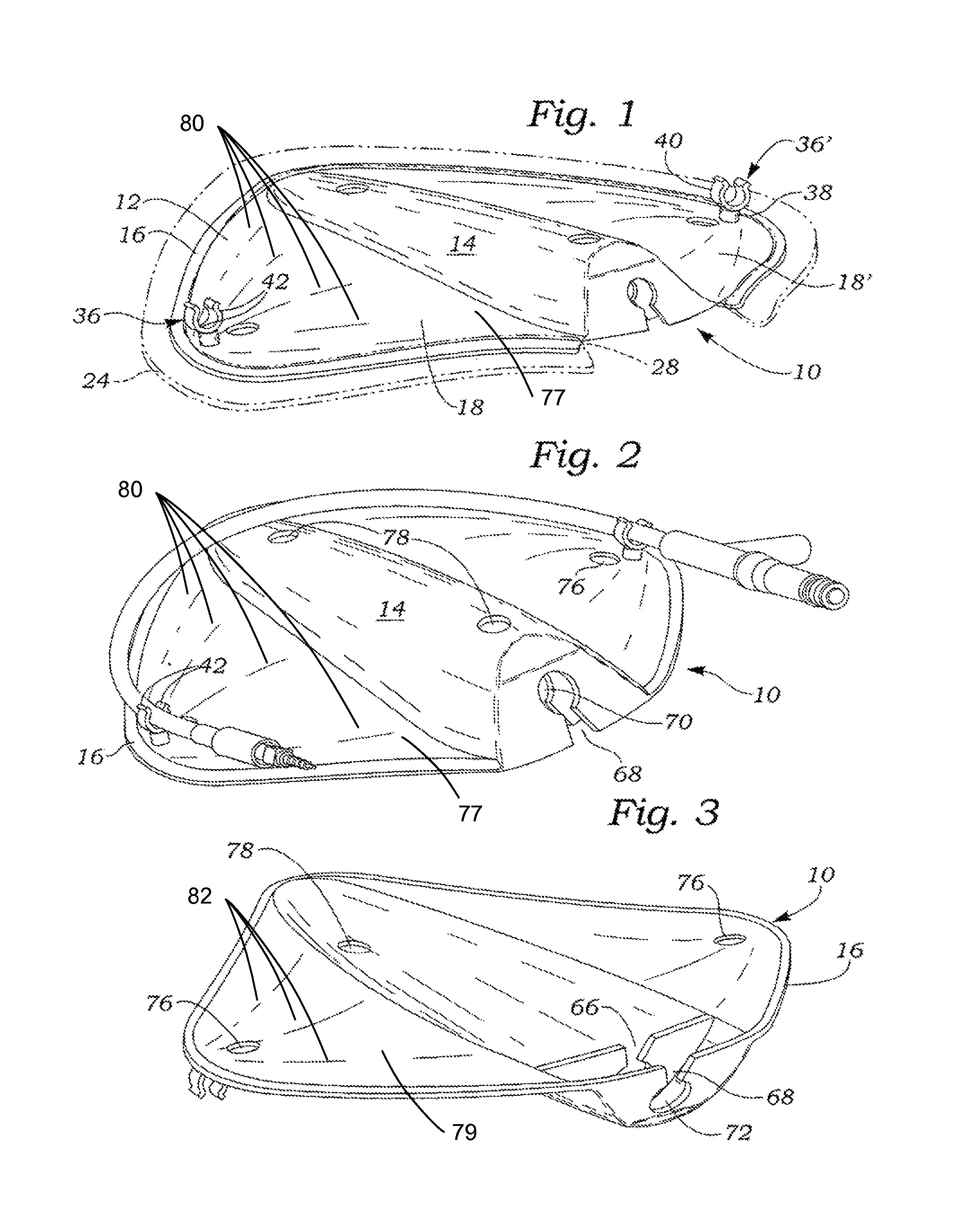
[0025]Referring now to the various figures of the drawing, the shield or cover 10 of the present invention is made of non-flexible material and includes a body 12 having a central chamber 14, an edge portion 16 extending about the perimeter of the body, and side portions 18, 18′ disposed on opposite sides of the chamber 14. As shown in FIGS. 1-3, the side portions 18, 18′ each include curved upper 77 and lower surfaces 79, which are depicted by use of curved lines 80 and 82. T...


PUM


Abstract

A protective cover or patch for covering and securing a catheter at the site of insertion of the needle into the patient's skin includes a single piece cover having a portion disposed about the perimeter of the patch bearing an adhesive coating and adapted for securement to a patients skin in the vicinity of the site of insertion, a bulbous chamber disposed inwardly of the perimeter portion, and a connecting portion disposed between the first portion and the chamber portion, the chamber portion defining a chamber for receiving one end of the catheter and extending substantially diametrically from one side of the perimeter to the other, and resilient tubing engagement elements positioned on opposite sides of the chamber. The chamber of the protective patch includes a roof portion raised above the plane defined by said perimeter of the patch.

Description

BACKGROUND OF THE INVENTION[0001]1. Field of the Invention[0002]The present invention relates to intravenous catheters, and more particularly to devices for securing catheters to the location at which the catheter is attached to the patient. Even more particularly, the present invention relates to a single piece article functioning to cover and secure a catheter at a location where the catheter has been inserted into the patient's skin, and a method of using the article.[0003]2. Description of the Related Art[0004]Typically, when a vascular catheter is placed, for example for intravenous administration of fluids, a combined catheter and needle is used to create the vascular puncture after which the needle is removed and the hub of the remaining catheter attached to a source of infusion liquid. Generally, It is necessary to stabilize the catheter in relation to the blood vessel to prevent movement of the catheter to preclude catheter withdrawal, undesirable additional blood vessel pu...

Claims


Application Information

Patent Timeline
Patent Type & Authority Patents(United States)
IPC IPC(8): A61M5/32A61M25/02A61M5/158
CPCA61M25/02A61M5/158A61M2025/0246A61M2025/0266
Inventor BENNETT, TIONNE ALLEN
Owner BENNETT TIONNE ALLEN
Learn More