Intravenous catheter protective cover

Active Publication Date: 2007-05-10
BENNETT TIONNE ALLEN
View PDF12 Cites 27 Cited by
  • Summary
  • Abstract
  • Description
  • Claims
  • Application Information

AI Technical Summary

Benefits of technology

[0010] The catheter cover structure provided in accordance with the invention was designed to provide an easy way to secure a catheter to a patient's skin at or in the vicinity of a catheter puncture site, while maintaining hygienic precautions and avoi

Problems solved by technology

Using precautions, such as sterile gloves, while inserting the catheters has made the process of securing these catheters complicated.
Indeed, in general, it is difficult to apply sticky tape to the skin while wearing gloves.
In addition, the extra movement needed to reach for and to apply such tape risks the loss of the unsecured catheter.
A difficulty encountered with such prior art products, however, is that the protective covering for the adhesive on the wings must

Method used


Image

  • Intravenous catheter protective cover
  • Intravenous catheter protective cover
  • Intravenous catheter protective cover

Examples


Embodiment Construction

[0024] The following description is provided to enable any person skilled in the art to make and use the invention and sets forth the best modes contemplated by the inventor of carrying out his invention. Various modifications, however, will remain readily apparent to those skilled in the art, since the generic principles of the present invention have been defined herein specifically to provide a novel construction and method for securing a catheter at the site of insertion of the catheter needle into a patient.

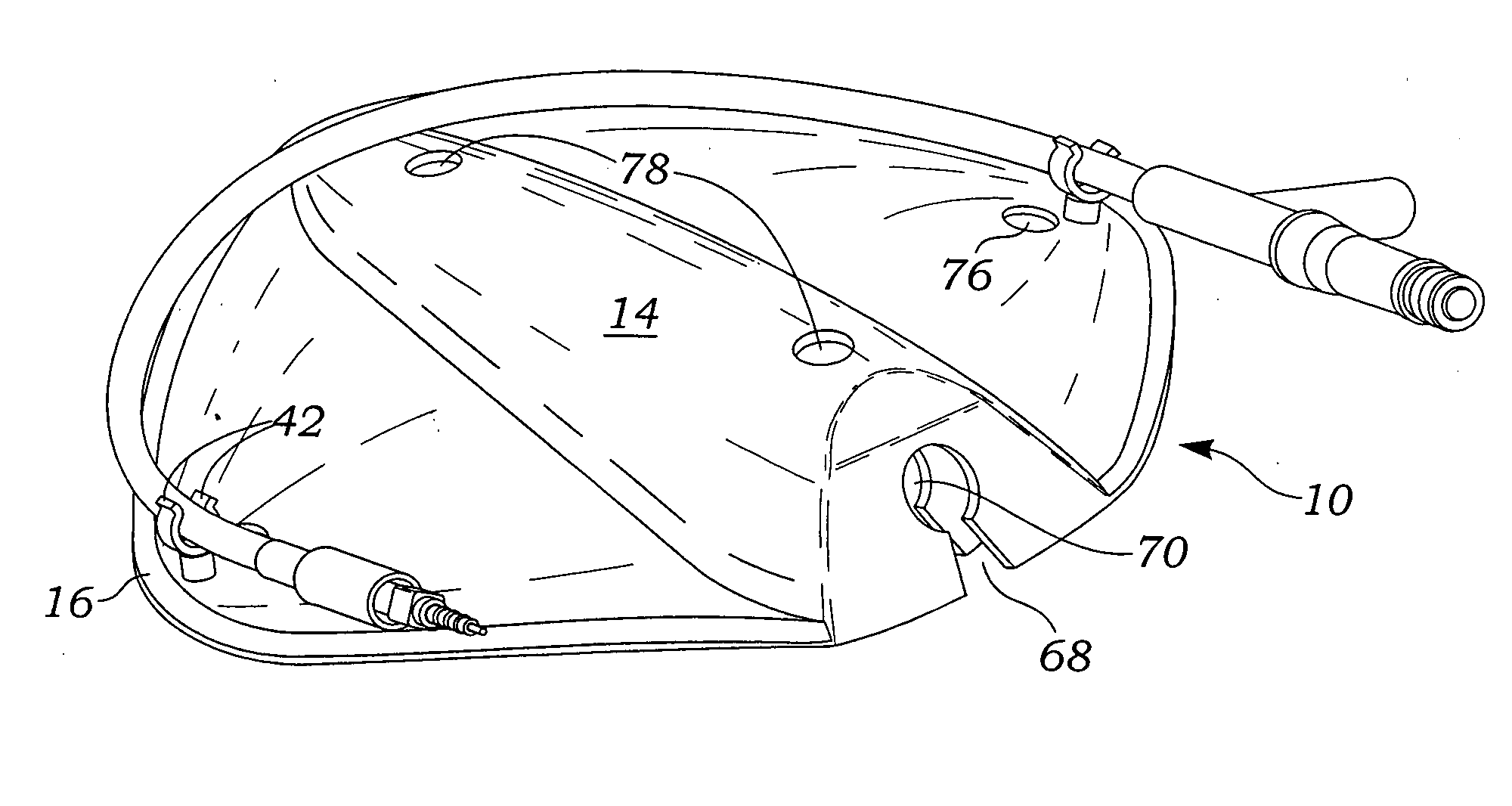
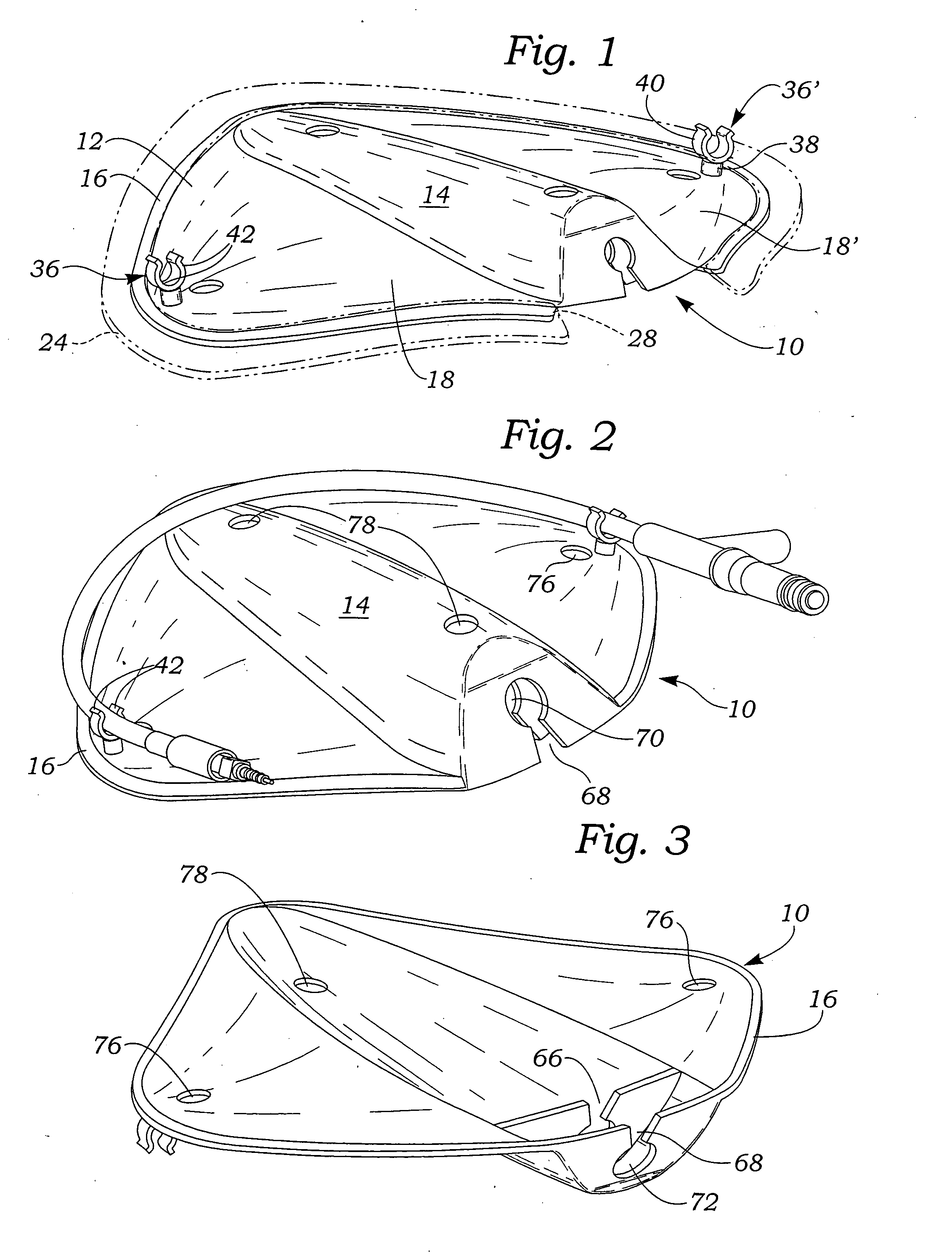
[0025] Referring now to the various figures of the drawing, the shield or cover 10 of the present invention is made of non-flexible material and includes a body 12 having a central chamber 14, an edge portion 16 extending about the perimeter of the body, and side portions 18, 18′ disposed on opposite sides of the chamber 14. The edge portion 16 is defined by a relatively narrow-width peripheral region arranged about the perimeter of the body, and preferably carries on its un...


PUM


Abstract

A protective cover or patch for covering and securing a catheter at the site of insertion of the needle into the patient's skin includes a single piece cover having a portion disposed about the perimeter of the patch bearing an adhesive coating and adapted for securement to a patients skin in the vicinity of the site of insertion, a bulbous chamber disposed inwardly of the perimeter portion, and a connecting portion disposed between the first portion and the chamber portion, the chamber portion defining a chamber for receiving one end of the catheter and extending substantially diametrically from one side of the perimeter to the other, and catheter securing means carried by the chamber portion. The catheter securing means of the protective patch includes catheter engagement means at one end of the chamber opposite to the insertion site, and is capable of resiliently engaging the catheter tubing. The catheter securing means of the patch further includes resilient tubing engagement elements positioned on opposite sides of the chamber. The chamber of the protective patch includes a roof portion raised above the plane defined by said perimeter of the patch, and the catheter securing means located opposite the insertion site comprises at least one end wall depending perpendicular to the chamber roof and being divided into two separated portions which together cooperate to resiliently and frictionally engage and secure said catheter.

Description

BACKGROUND OF THE INVENTION [0001] 1. Field of the Invention [0002] The present invention relates to intravenous catheters, and more particularly to devices for securing catheters to the location at which the catheter is attached to the patient. Even more particularly, the present invention relates to a single piece article functioning to cover and secure a catheter at a location where the catheter has been inserted into the patient's skin, and a method of using the article. [0003] 2. Description of the Related Art [0004] Typically, when a vascular catheter is placed, for example for intravenous administration of fluids, a combined catheter and needle is used to create the vascular puncture after which the needle is removed and the hub of the remaining catheter attached to a source of infusion liquid. Generally, It is necessary to stabilize the catheter in relation to the blood vessel to prevent movement of the catheter to preclude catheter withdrawal, undesirable additional blood v...

Claims


Application Information

Patent Timeline
IPC IPC(8): A61M5/32
CPCA61M5/158A61M25/02A61M2025/0246A61M2025/0266
Inventor BENNETT, TIONNE ALLEN
Owner BENNETT TIONNE ALLEN
Why Eureka
Try Eureka