Device for a special effect explosion or burst

a special effect and device technology, applied in the field of special effects technology, can solve the problems of insufficiently addressing safety and consistency concerns, affecting the safety of actors and other participants, and affecting the performance of the actor

Active Publication Date: 2017-01-03
8879192 CANADA INC
View PDF6 Cites 2 Cited by
  • Summary
  • Abstract
  • Description
  • Claims
  • Application Information

AI Technical Summary

Problems solved by technology

Furthermore, mechanical special effects are distinguishable from in-camera photographic special effects or computer generated special effects in that mechanical special effects accomplished during live-action filming or live-action productions can be apparent to the actors and other participants, and pose a safety risk to these actors and other participants.
The actor's costume is worn over these components and coupled to the pouch containing fake blood so that when the detonator / squib is electrically triggered the resulting explosion ruptures the pouch splattering the fake blood contents away from the actor's body and onto and / or through the actor's costume resulting in staining of the actor's costume.
Despite the recognition of these concerns many bullet hit devices continue to be hand-made and constructed in an ad-hoc fashion, and do not sufficiently address safety and consistency concerns.

Method used


Image

  • Device for a special effect explosion or burst
  • Device for a special effect explosion or burst
  • Device for a special effect explosion or burst

Examples


Embodiment Construction

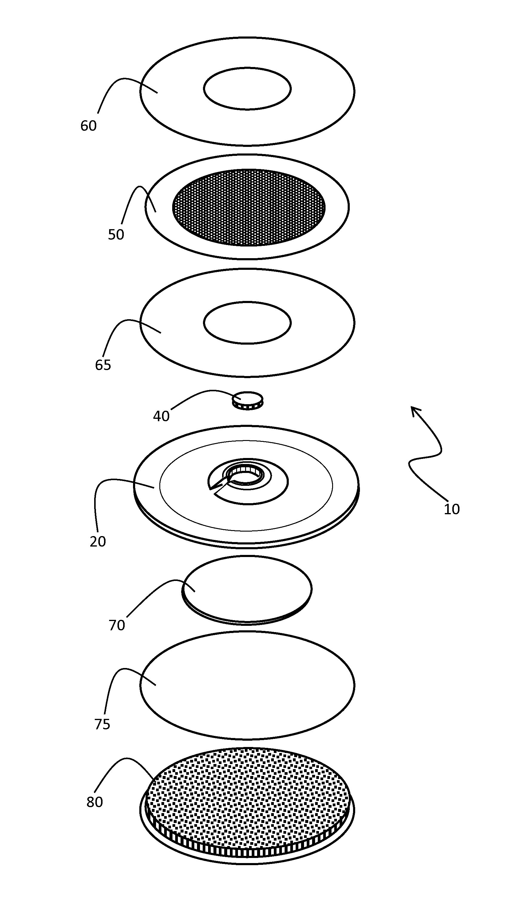
[0024]Terms top, bottom, front, back may be used to describe surfaces of a bullet hit device or components therein. The terms top and front are used interchangeably to describe a surface of the harness that provides a receptacle for housing a squib charge, while the back and bottom interchangeably reference the opposing surface of the harness. Top / front or bottom / back surfaces of other components are consistent with the orientation provided by the harness.

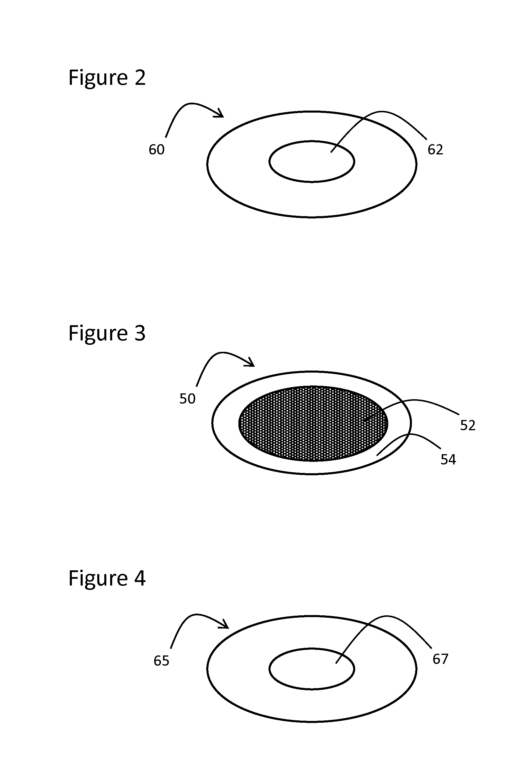
[0025]Referring now to the drawings FIG. 1 shows an exploded view of a bullet hit device 10. The bullet hit device 10 comprises a harness 20 providing a centrally located receptacle for housing a squib charge 40, a plastic bag 50 filled with a special effect blood medium coupled to a front side of the harness, and a metal plate 70 and a foam pad 80 coupled to a back side of the harness. First and second O-ring double-sided mounting tapes 60 and 65 are attached to opposing surfaces of the plastic bag 50. The first O-ring double-side...


PUM


Abstract

A harness for receiving a special effects squib charge includes: a substantially planar base bound by opposing first and second surfaces joined at a perimeter; a tubular sidewall extending from the first surface of the base to form a tubular receptacle; an inward extension from the tubular sidewall defining a receiving aperture, the receiving aperture sized to be elastically deformed to allow insertion of the squib charge; and the distance between the base and the inward extension sized to be substantially equal to the axial length of the squib charge. A bullet hit device includes the harness, and a kit is for assembly and / or use of the harness as a bullet hit device.

Description

CROSS REFERENCE TO RELATED APPLICATIONS[0001]This application is the U.S. National Phase of International Application No. PCT / CA2014 / 051177, filed Dec. 5, 2014, designating the U.S. and published in English as WO 2015 / 081447 on Jun. 11, 2015 which claims the benefit of U.S. Provisional Patent Application No. 61 / 912,728 filed Dec. 6, 2013. Any and all applications for which a foreign or domestic priority claim is identified here or in the Application Data Sheet as filed with the present application are hereby incorporated by reference under 37 CFR 1.57.BACKGROUND OF THE INVENTION[0002]1. Field of the Invention[0003]The present invention relates generally to special effects technology, and more particularly mechanical special effects for controlled and illusory explosions or bursts.[0004]2. Description of the Related Art[0005]Special effects (often abbreviated as SFX, SPFX, or simply FX) are illusions used in staged settings or productions such as film, television, theatre, video game...

Claims


Application Information

Patent Timeline
Patent Type & Authority Patents(United States)
IPC IPC(8): A63J7/00A63J5/02A63J5/04
CPCA63J7/00A63J5/02A63J5/04
Inventor TESTA, MARTIN TIMOTHY
Owner 8879192 CANADA INC
Why Eureka
Try Eureka