Headrest mounting structure vehicle seat

a technology for mounting structures and vehicle seats, which is applied to head rests, vehicle components, vehicle arrangements, etc., can solve the problems of achieve the effects of preventing a rattle caused by the gap, and reducing the workability of insertion operations

Active Publication Date: 2017-01-17
TOYOTA BOSHOKU KK
View PDF3 Cites 1 Cited by
  • Summary
  • Abstract
  • Description
  • Claims
  • Application Information

AI Technical Summary

Benefits of technology

[0007]The invention provides a headrest mounting structure of a vehicle seat capable of preventing a rattle occurring between a holder and a support and suppressing an increase in insertion force required when the support is inserted into a support hole of the holder.

Problems solved by technology

Consequently, there is a possibility that workability of the insertion operation is reduced.

Method used


Image

  • Headrest mounting structure vehicle seat
  • Headrest mounting structure vehicle seat
  • Headrest mounting structure vehicle seat

Examples


Embodiment Construction

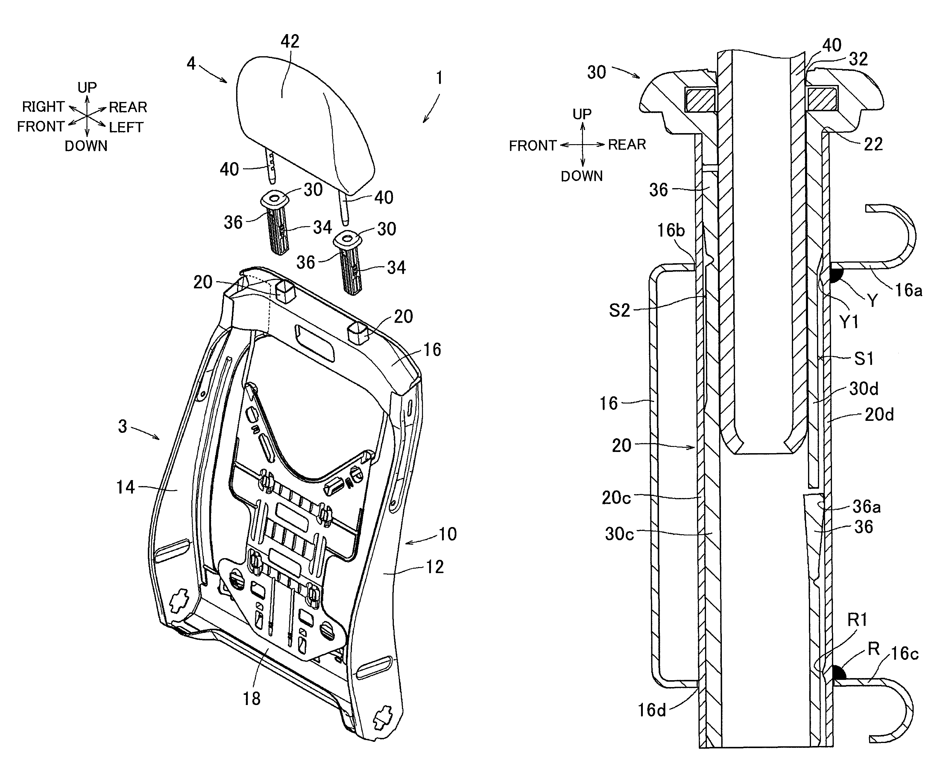
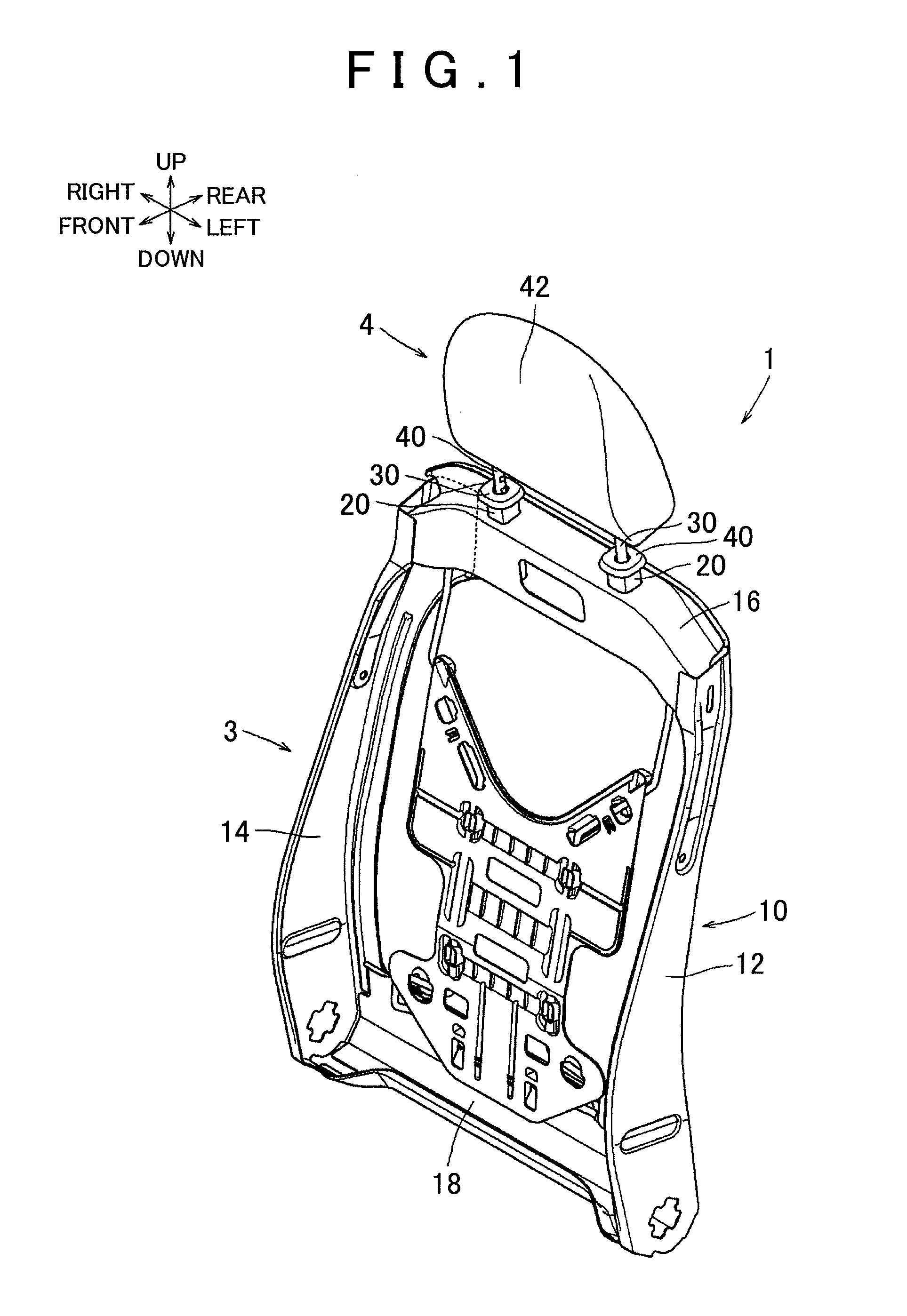
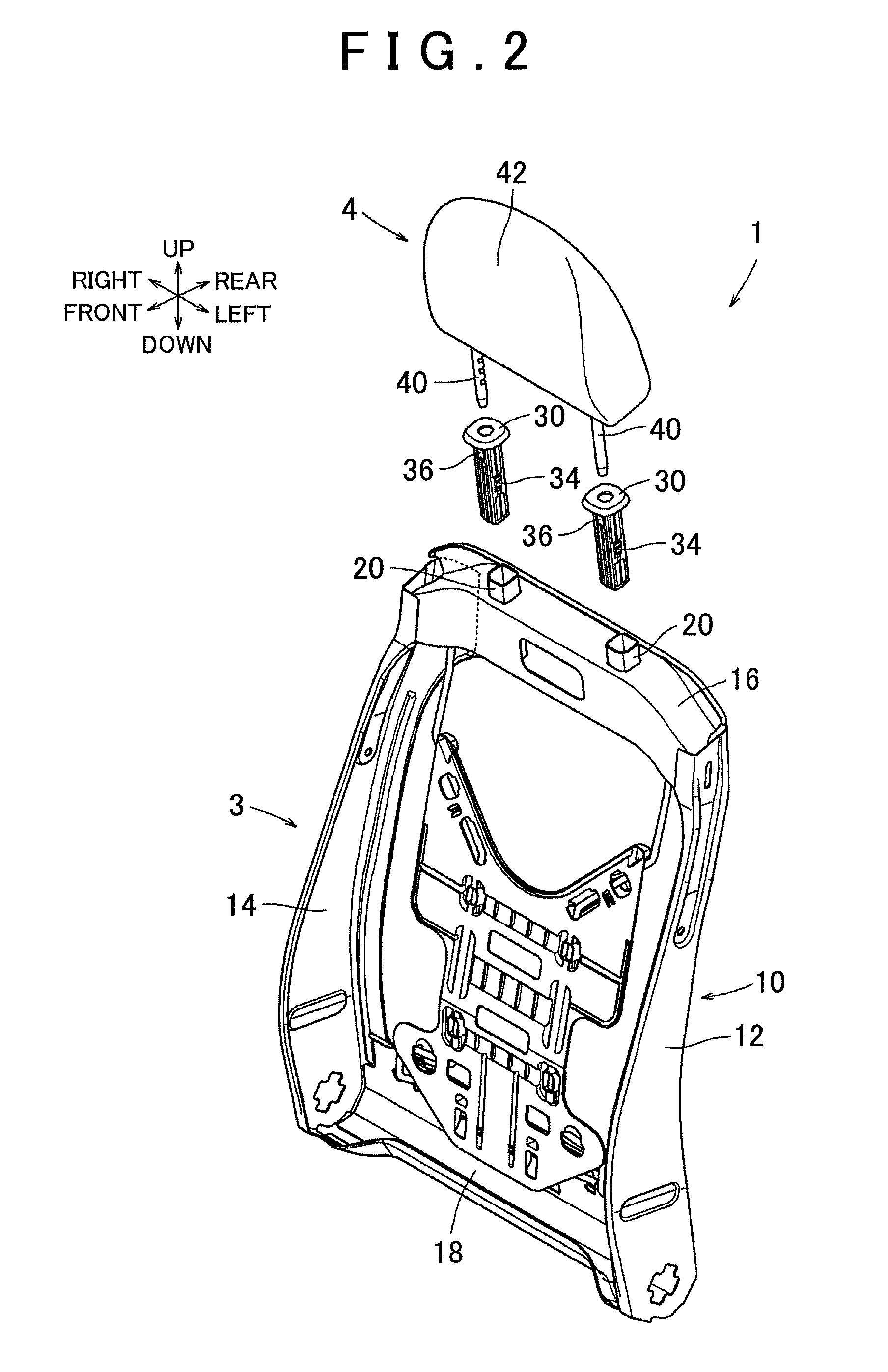
[0027]Hereinbelow, an embodiment of the invention will be described by using FIGS. 1 to 11. Note that, in the following description, as an example of a “vehicle seat”, a “vehicle seat 1” mounted on an automobile (not shown) will be described. In addition, as an example of a “gap occupying part”, an “elastic piece 36” will be described. Further, in the following description, up, down, front, rear, left, and right denote up, down, front, rear, left, and right directions described in the above drawings, i.e., up, down, front, rear, left, and right directions when a state in which the vehicle seat 1 is installed to the automobile is used as a reference.

[0028]With reference to FIGS. 1 to 5, the schematic configuration of the vehicle seat 1 according to the embodiment of the invention will be described first. Note that, depiction of a pad and a cover is omitted in order to clarify a structure of an internal framework of the vehicle seat 1 in FIGS. 1 and 2. The vehicle seat 1 serves as, e....


PUM


Abstract

A headrest is mounted to a seat back by inserting a support into a support hole of a holder and inserting a stay of the headrest into to stay hole of the support inserted into the support hole of the holder. A gap occupying part provided in the support moves between an advanced position at which the gap occupying part protrudes from an outer wall of the support and is capable of touching an inner surface of the support hole, and a retracted position at which the gap occupying part is retracted to an inner side of the stay hole from the advanced position. The gap occupying part moves toward the retracted position from the advanced position when the support is inserted into the support hole, and moves toward the advanced position when the stay is inserted into the stay hole.

Description

INCORPORATION BY REFERENCE[0001]The disclosure of Japanese Patent Application No. 2014-091067 filed on Apr. 25, 2014 including the specification, drawings and abstract is incorporated herein by reference in its entirety.BACKGROUND OF THE INVENTION[0002]1. Field of the Invention[0003]The invention relates to a headrest mounting structure of a vehicle seat, and particularly relates to a headrest mounting structure of a vehicle seat in which the headrest is mounted to a seat back by inserting a support into a support hole of a holder mounted to the seat back and inserting a stay of the headrest into a stay hole of the support inserted into the support hole.[0004]2. Description of Related Art[0005]Conventionally, a headrest of a vehicle seat is mounted to a seat back by inserting a support into a support hole of a holder mounted to the seat back and inserting a stay of the headrest into a stay hole of the support inserted into the support hole. Herein, Japanese Patent Application Public...

Claims


Application Information

Patent Timeline
Patent Type & Authority Patents(United States)
IPC IPC(8): B60N2/48
CPCB60N2/4826B60N2002/4897B60N2/803B60N2/838B60N2/826B60N2/80B60N2/897
Inventor KITOU, HIDEKAZUOZAKI, AKIHIDE
Owner TOYOTA BOSHOKU KK
Why Eureka
Try Eureka