
Method and device for monitoring data relating to the tires of a vehicle

a technology for monitoring data and tires, applied in the direction of vehicle components, tire measurements, devices using electric/magnetic means, etc., can solve the problems of increasing the cost of components, increasing the complexity of the overall system, and limited number of radio frequencies, so as to achieve the effect of improving and improving speed

Active Publication Date: 2017-01-31
CONTINENTAL AUTOMOTIVE FRANCE +1
View PDF19 Cites 0 Cited by
  • Summary
  • Abstract
  • Description
  • Claims
  • Application Information

AI Technical Summary

Benefits of technology

The invention provides a faster and more accurate method for identifying and locating wheel units on a vehicle after driving interruptions. This method uses existing sensors on the vehicle and requires fewer components.

Problems solved by technology

These methods, which explicitly implement the initialization process (recognition of identifiers related to the vehicle) and the locating process in a single step are generally associated with increased component costs and with a relatively overall system high degree of complexity.
However, the number of radio frequencies is limited.
However, the described approaches can lead to false conclusions or to no conclusion at all if two or more vehicles move one beside the other or one behind the other for a relatively long period of time.
This can arise when the vehicle is in heavy traffic conditions.
The locating of new tire positions, carried out after each relatively long stoppage of the vehicle, has the main drawback of the tire pressure monitoring system being occupied for a relatively long time for the correct assigning of identifiers and of wheel units corresponding positions, before the system can evaluate the measured air pressures in the normal operating mode and assign them to a corresponding wheel unit position on the vehicle.
Either case constitutes a real safety risk.

Method used


Image

  • Method and device for monitoring data relating to the tires of a vehicle
  • Method and device for monitoring data relating to the tires of a vehicle
  • Method and device for monitoring data relating to the tires of a vehicle

Examples


Embodiment Construction

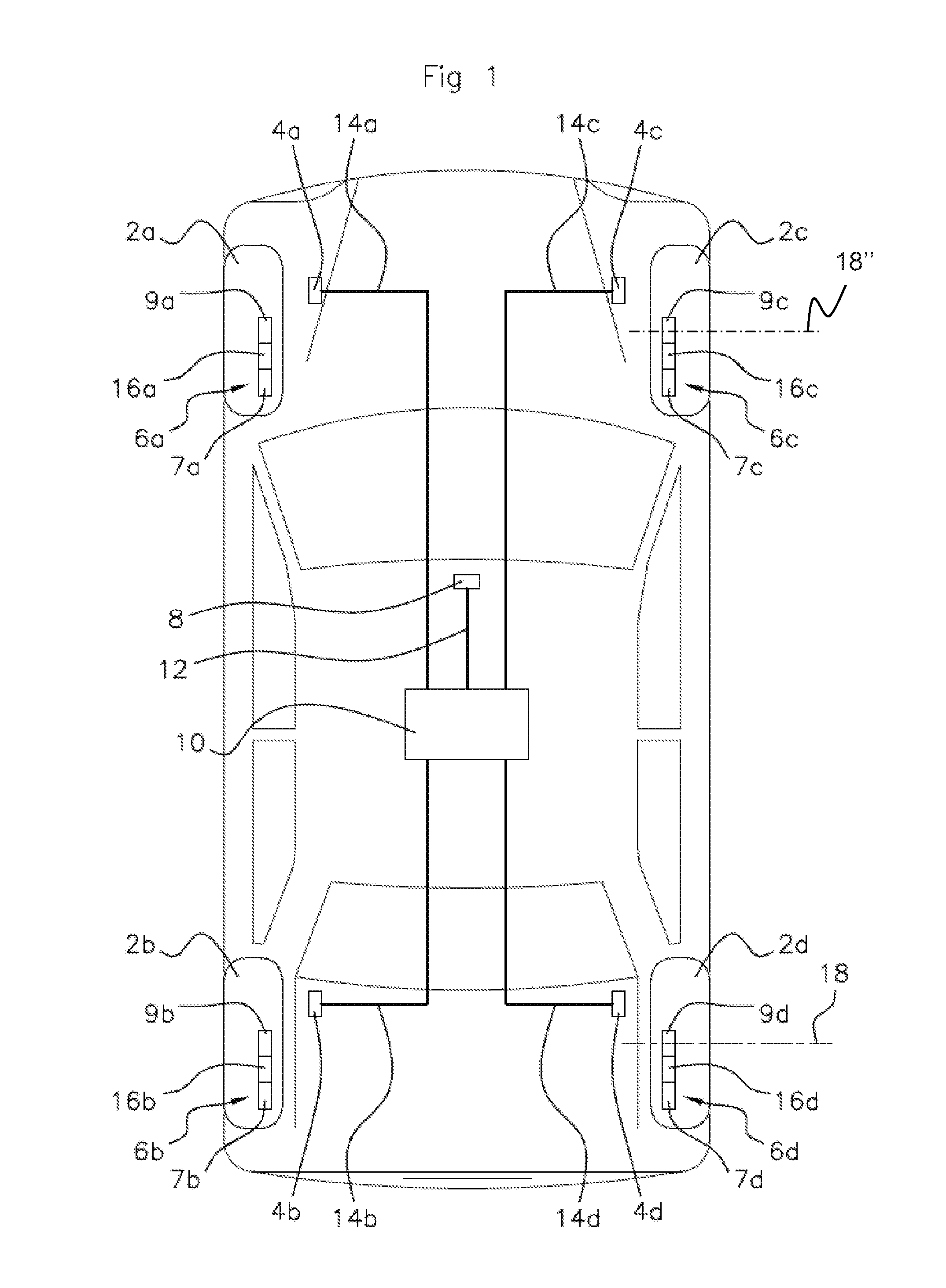
[0037]FIG. 1 schematically shows a vehicle including wheels 2a to 2d, each wheel able to turn around an axis 18. The vehicle includes a tire pressure monitoring system which in turn includes wheel units 6a to 6d. Each wheel unit includes a pressure sensor, 7a to 7d respectively, fitted to the tire of the wheel, 2a to 2d respectively, of the vehicle. For example, the pressure sensor is located inside the tire tube or is associated with the tire tube valve. The wheel units 6a to 6d include transmitters, 9a to 9d respectively, which provide for transmitting data to a contactless receiver 8 (an antenna).

[0038]Furthermore, the wheel units 6a to 6d include angular sensors, 16a to 16d respectively. Each angular sensor 16a to 16d provides for recognizing at least one fixed angular position of the wheel around its axis 18. Each angular sensor can have the shape of a flexible component as described, for example in U.S. Pat. No. 6,112,587 in the name of Continental (registered trademark).

[0039...


PUM


Abstract

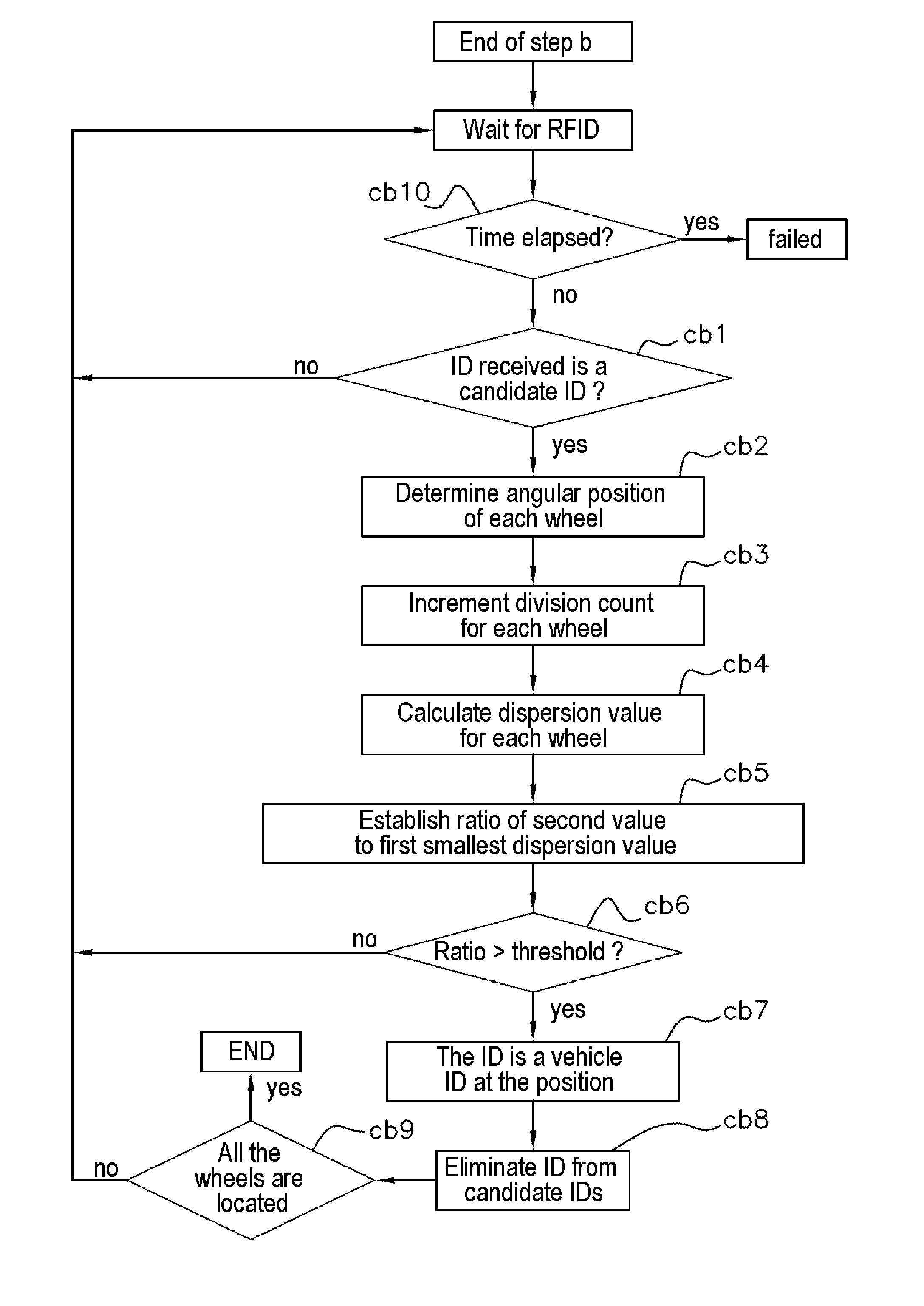
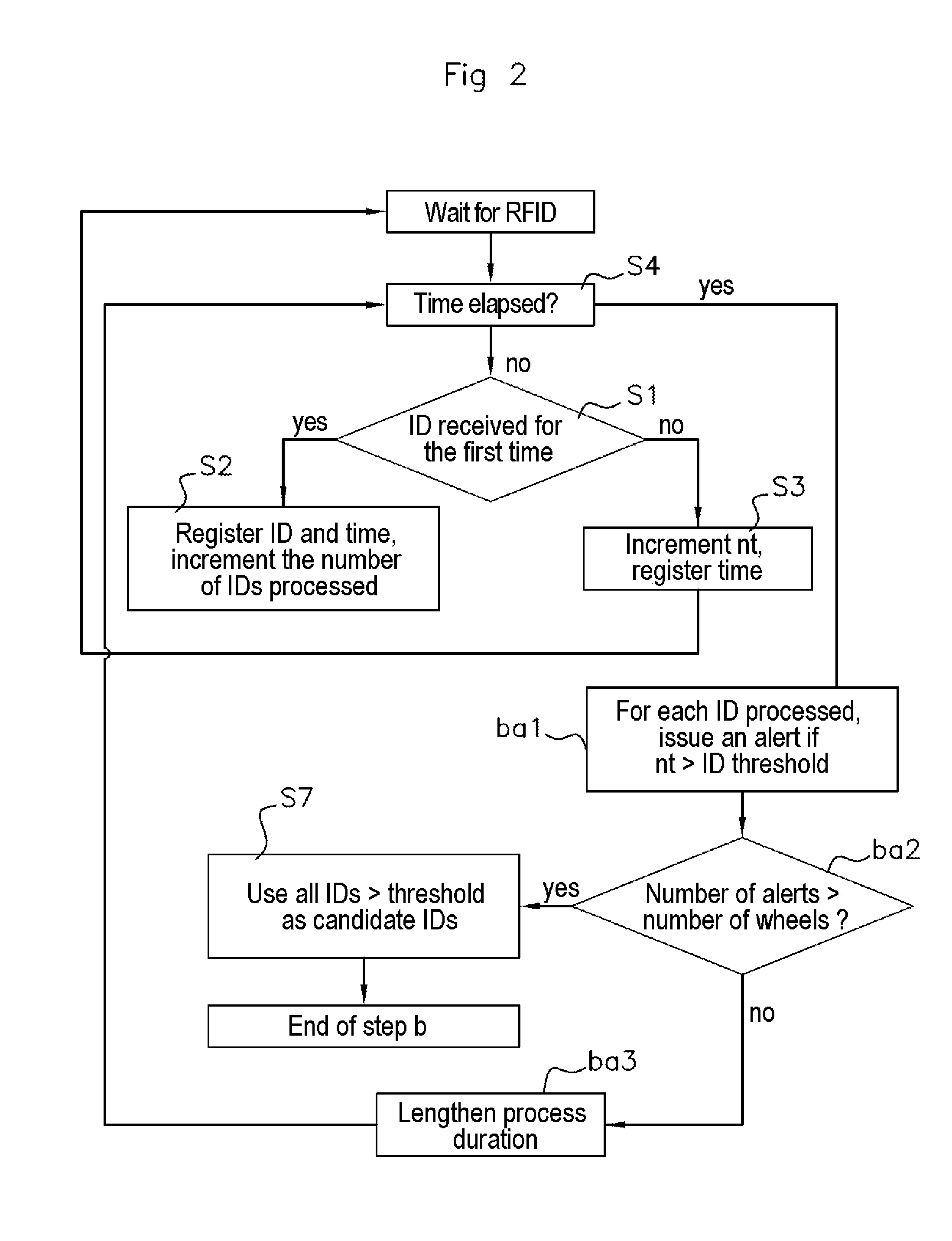
In a method for determining identifiers of wheel units and positions relative to the vehicle of the wheels on which the wheel units are fitted, the vehicle is equipped with a speed sensor for each wheel and elements for transmitting at a predetermined angular position of the corresponding wheel about its axis a message including the identifier of the wheel unit. A central processing unit receives the message and information from the speed sensors. The method includes a) counting, for each identifier, of a number “nt” of receptions of the identifier, b) statistical processing of the numbers “nt” to determine candidate identifiers of a wheel unit of the vehicle, until the number of candidate identifiers at least equals the number of wheels, and c) determining that a candidate identifier is the identifier of a wheel unit if the candidate identifier meets a predetermined criterion.

Description

BACKGROUND OF THE INVENTION[0001]Field of the Invention[0002]The invention relates to a system for monitoring data from vehicle tires, for example a tire pressure monitoring system and more particularly a method for determining the position (on the vehicle) of a tire having a unique identification number (ID). This tire position can be each of the following positions: front left (FL), front right (FR), rear left (RL), rear right (RR).[0003]Description of the Related Art[0004]Known tire pressure monitoring systems (TPMS) comprise a wheel unit installed in each wheel, a reception antenna on the vehicle, and a central processing unit fitted to the vehicle to monitor the pressures of the tires. Each wheel unit comprises a transmitter to transfer the data from sensors installed in the wheel units. Said sensors can be chosen from a group comprising: a pressure sensor which measures the internal air pressure of the tire, a temperature sensor which measures the temperature of the air inside...

Claims


Application Information

Patent Timeline
IPC IPC(8): B60C23/00B60C23/06G01M17/013
CPCB60C23/00B60C23/061G01M17/013B60C23/0416B60C23/0489B60C23/04B60C23/06G01P3/44
Inventor FINK, ALEXANDERGUINART, NICOLASKUCHLER, GREGORSPOTKA, JURGENPFLUGMANN, MARC
Owner CONTINENTAL AUTOMOTIVE FRANCE
Learn More