Frame and roof system for a portable shelter

a portable shelter and frame technology, applied in the direction of fencing, buildings, constructions, etc., can solve the problems of preventing the shelter from being assembled at all, consuming time and labor of conventional portable shelters, and requiring a great deal of time to assemble and disassembl

Active Publication Date: 2017-01-31
SUNJOY INDS GROUP
View PDF40 Cites 36 Cited by
  • Summary
  • Abstract
  • Description
  • Claims
  • Application Information

AI Technical Summary

Problems solved by technology

Although, conventional portable shelters often require a great deal of time to assemble and disassemble because they include a large collection of constituent components that must be fastened together using a plurality of different tools.
Not only is the assembly of these conventional portable shelters time consuming, but it is also inconvenient, the users of such shelters are required to carry around a variety of different tools each time they want to assemble their portable shelter in a remote location.
Also, if they accidently forget to bring one of the tools that is necessary to assemble the portable shelter, they may be precluded from assembling the shelter at all.

Method used


Image

  • Frame and roof system for a portable shelter
  • Frame and roof system for a portable shelter
  • Frame and roof system for a portable shelter

Examples


first embodiment

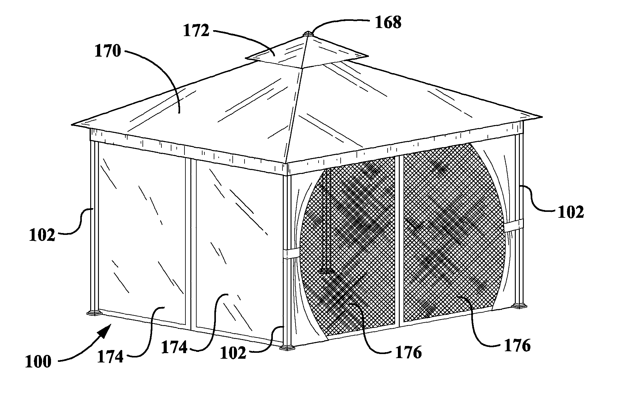
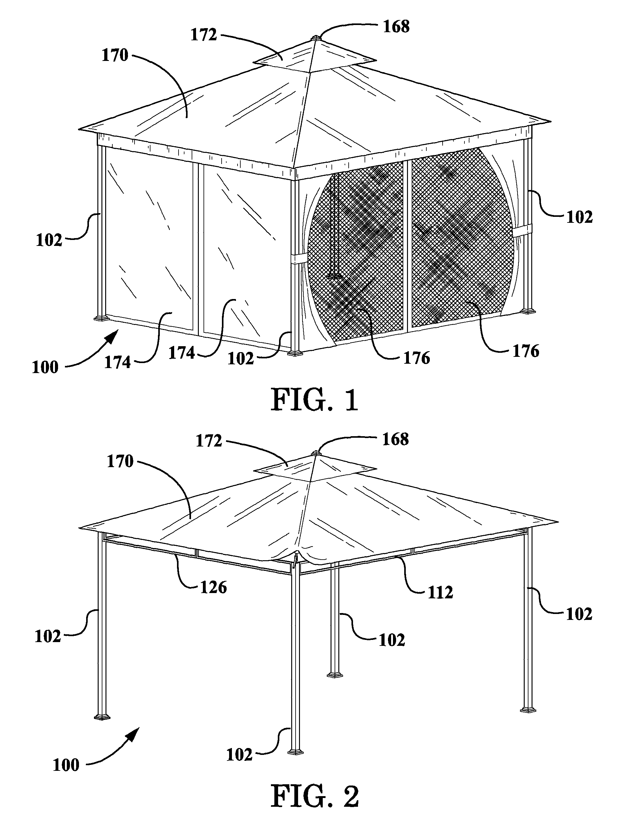
[0034]FIG. 1 is a perspective view of a portable shelter, according to the invention, wherein the side panels and the roof canopy are shown disposed on the portable shelter;

[0035]FIG. 2 is another perspective view of the portable shelter, according to the first embodiment of the invention, wherein the side panels have been removed from the portable shelter;

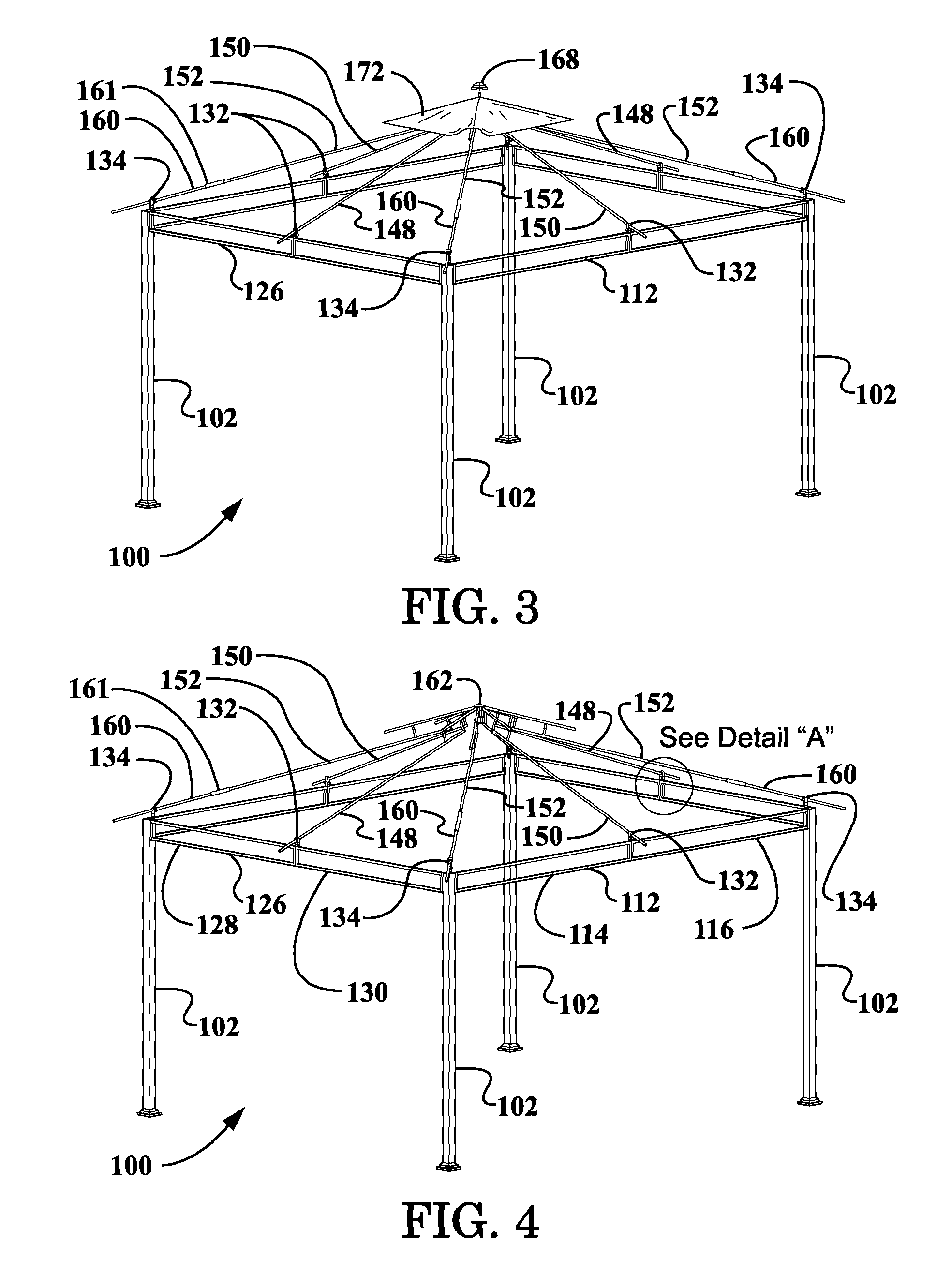
[0036]FIG. 3 is yet another perspective view of the portable shelter, according to the first embodiment of the invention, wherein both the side panels and the peripheral roof canopy portion have been removed from the portable shelter to better illustrate the framing system thereof;

[0037]FIG. 4 is still another perspective view of the portable shelter, according to the first embodiment of the invention, wherein the side panels, the peripheral roof canopy portion, and the central roof canopy portion have all been removed from the portable shelter to better illustrate the framing system thereof;

[0038]FIG. 5 is a partial perspective v...

second embodiment

[0052]FIG. 19 is an overall exploded perspective view of a portable shelter framing system, according to the invention, wherein the four post-type portable shelter is not provided with framing for a roof vent;

third embodiment

[0053]FIG. 20 is an overall exploded perspective view of a portable shelter framing system, according to the invention, wherein a folding corner panel-type portable shelter is provided with framing for a roof vent;


PUM


Abstract

A portable shelter framing system is disclosed herein. The portable shelter framing system includes a plurality of corner support members; a plurality of crossbeam members, each of the crossbeam members configured to be connected between a pair of the plurality of corner support members without the use of tools; and a plurality of roof frame members, each of the roof frame members configured to be coupled to one of the plurality of corner support members or one of the plurality of crossbeam members without the use of tools. In one or more embodiments, the portable shelter framing system further includes a plurality of connecting members, each of the connecting members configured to couple a respective one of the plurality of roof frame members to a respective one of the plurality of corner support members or to a respective one of the plurality of crossbeam members without the use of tools.

Description

CROSS-REFERENCE TO RELATED APPLICATIONS[0001]This patent application is a continuation-in-part application, which is co-pending with, and claims priority from, U.S. Non-Provisional patent application Ser. No. 14 / 091,644, entitled “Frame and Roof System for a Portable Shelter”, filed on Nov. 27, 2013, which is incorporated by reference herein in its entirety by this reference thereto.STATEMENT REGARDING FEDERALLY SPONSORED RESEARCH OR DEVELOPMENT[0002]Not Applicable.NAMES OF THE PARTIES TO A JOINT RESEARCH AGREEMENT[0003]Not Applicable.INCORPORATION BY REFERENCE OF MATERIAL SUBMITTED ON A COMPACT DISK[0004]Not Applicable.BACKGROUND OF THE INVENTION[0005]1. Field of the Invention[0006]The invention generally relates to portable shelter framing systems. More particularly, the invention relates to portable shelter framing systems that are configured to be assembled without the use of tools.[0007]2. Background and Description of Related Art[0008]Portable shelters, such as outdoor gazebos...

Claims


Application Information

Patent Timeline
Patent Type & Authority Patents(United States)
IPC IPC(8): E04H15/18E04B7/00E04H15/48E04H15/34E04H15/16
CPCE04H15/18E04B7/00E04H15/16E04H15/34E04H15/48E04H15/02E04H15/54E04H17/18
Inventor HUNT, DAVID LEWISSCHMIDT, GILBERT CARLBANAL, SEAN MICHAELPAN, LIANZHANG
Owner SUNJOY INDS GROUP
Why Eureka
Try Eureka