
Detection of lost wafer from spinning chuck

a technology of microelectronic substrate and chuck, which is applied in the direction of electrical apparatus, basic electric elements, and testing/measurement of semiconductor/solid-state devices. it can solve the problems of substrate breakage, damage to the process chamber, and the microelectronic substrate may become unsecured from the rotating mechanism

Inactive Publication Date: 2017-02-07
TEL EPION
View PDF10 Cites 7 Cited by
  • Summary
  • Abstract
  • Description
  • Claims
  • Application Information

AI Technical Summary

Benefits of technology

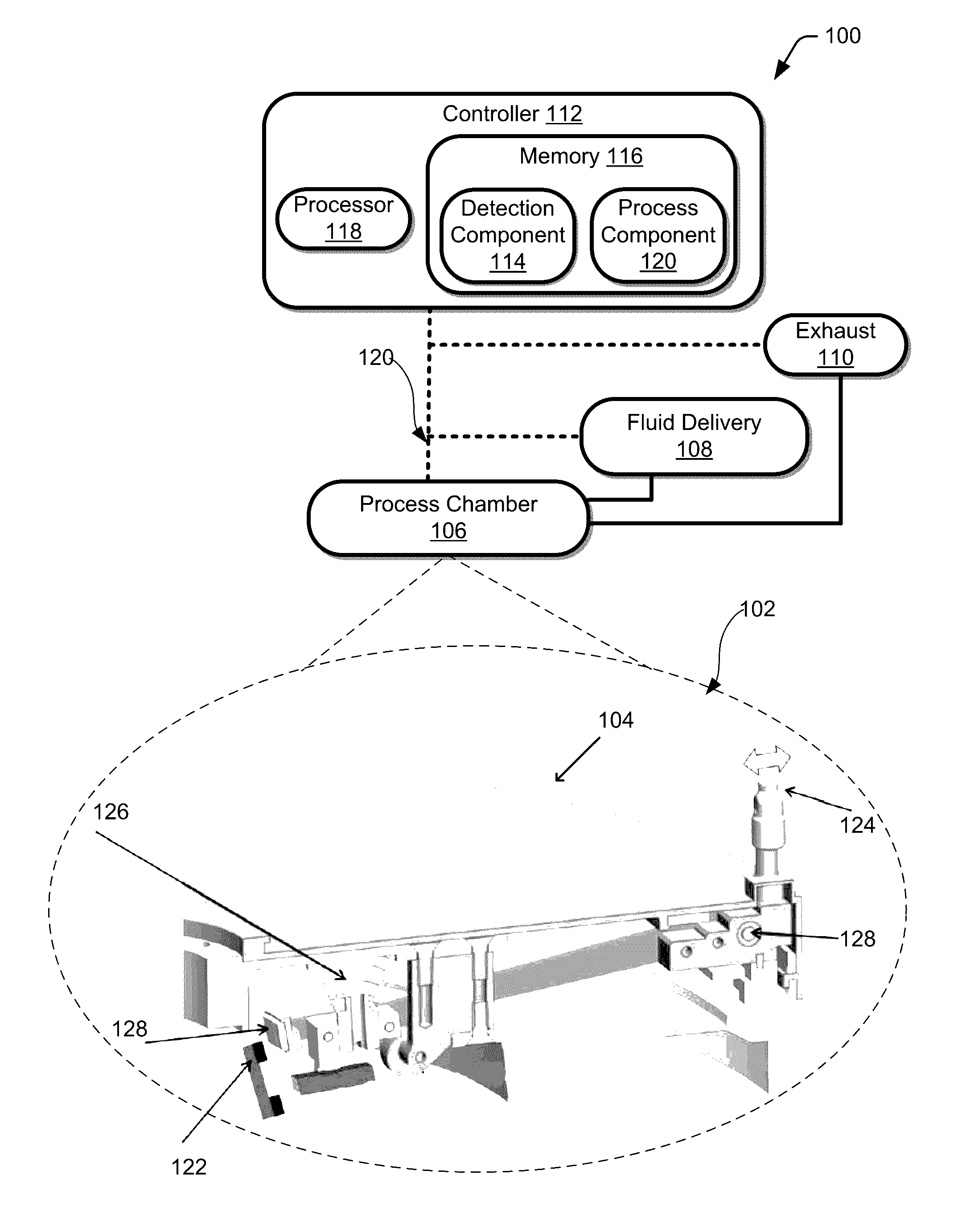
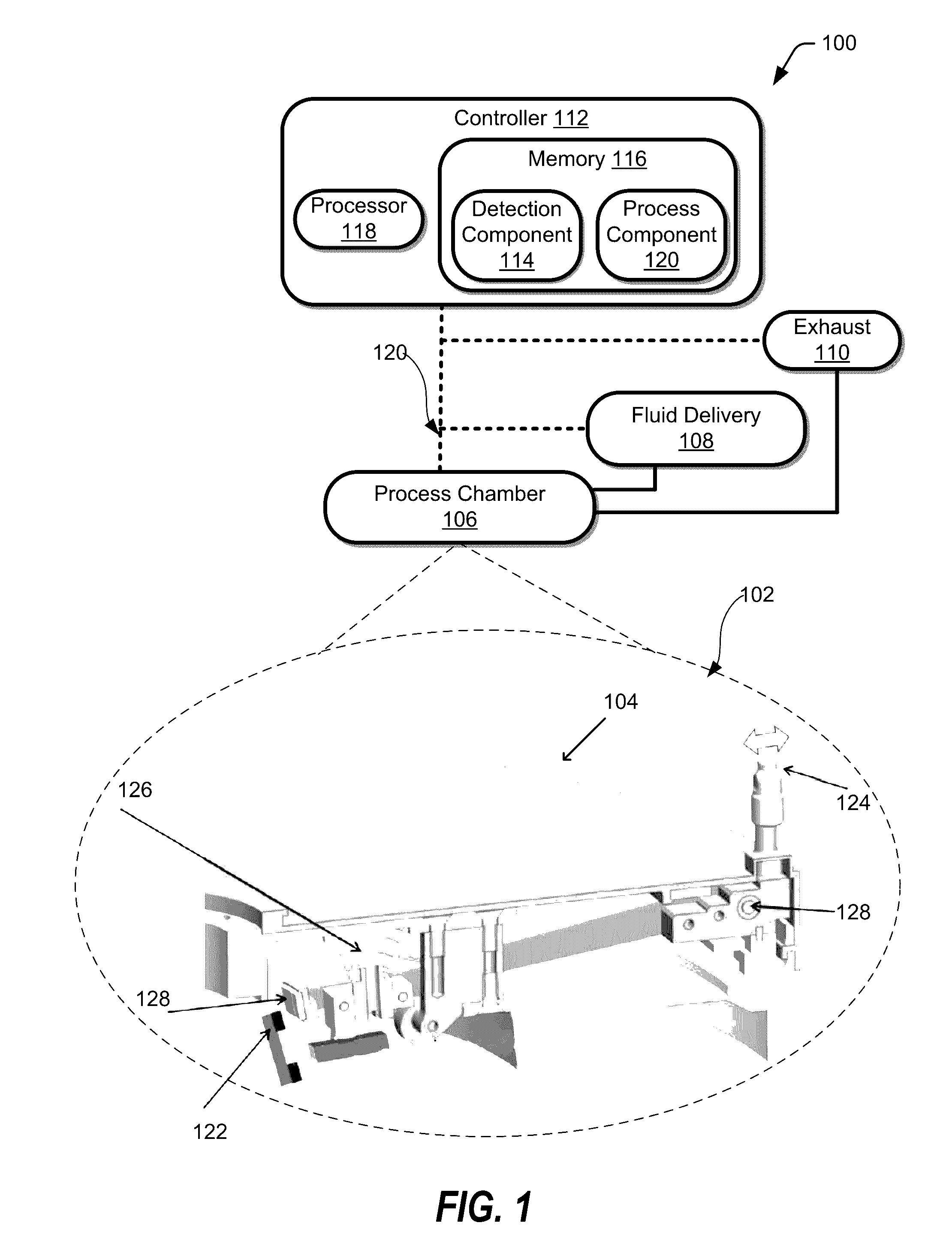
[0004]One approach to preventing or minimizing damage to the process equipment, may include a microelectronic substrate detection system that determines whether the microelectronic substrate is secured prior to and during the rotation of the microelectronic substrate. In one embodiment, the microelectronic substrate may be gripped, using any mechanical means (e.g., clamp) that secures the microelectronic substrate in desired position for subsequent treatment that may include rotating the microelectronic substrate. The gripping mechanism positioning may be monitored by the detection system, such that if the mechanism changes position in an undesirable manner, the detection system can shut down the rotation to minimize process chamber damage.
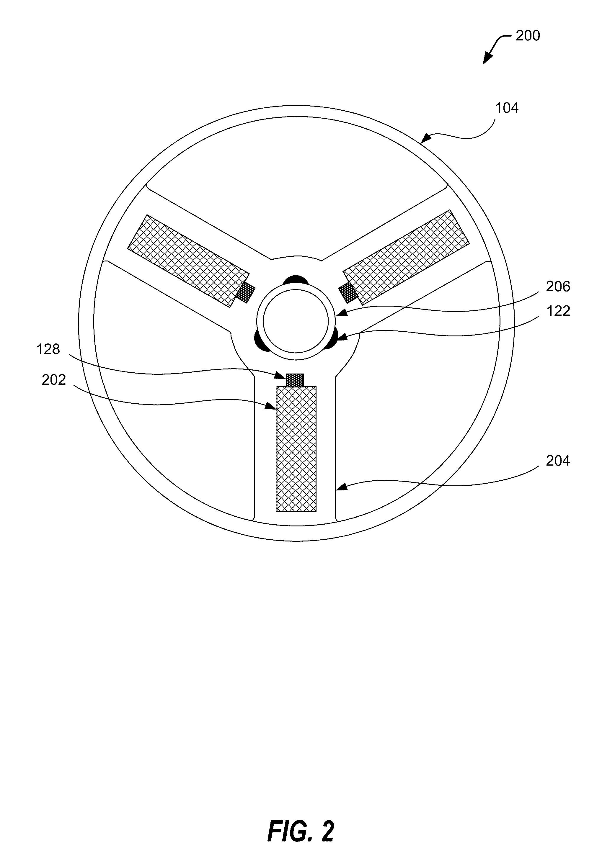
[0007]In one embodiment, three or more magnets may be disposed adjacent to the gripping components, such that the movement or orientation of the gripping components alters the position and / or orientation of the magnets relative to the detection sensors. The detection system may identify the position or orientation of the magnets based, at least in part, on the field strength magnitude and / or changes in field strength. In this embodiment, the position of the gripping components may be correlated to field strengths that are indicative of a secure microelectronic substrate. However, when the field strengths exceed, or go below, a threshold amount of a trigger value, this may indicate the microelectronic substrate may no longer be secured to the rotation mechanism. Accordingly, the rotation mechanism may begin to slow down or be shut off to minimize further damage to the process chamber caused by an unsecured microelectronic substrate.

Problems solved by technology

However, in some instances, the microelectronic substrate may become unsecured from the rotating mechanism.
This may cause breakage of the substrate and damage to the process chamber, which may be increased if the rotating mechanism continues to rotate and projects portions of the broken microelectronic substrate throughout the chamber.
However, if the microelectronic substrate becomes unsecured, the mechanical tension applied by the gripping component may also change position or orientation.

Method used


Image

  • Detection of lost wafer from spinning chuck
  • Detection of lost wafer from spinning chuck
  • Detection of lost wafer from spinning chuck

Examples


Embodiment Construction

[0016]Methods for selectively removing material from a substrate are described in various embodiments. One skilled in the relevant art will recognize that the various embodiments may be practiced without one or more of the specific details, or with other replacement and / or additional methods, materials, or components. In other instances, well-known structures, materials, or operations are not shown or described in detail to avoid obscuring aspects of various embodiments of the invention. Similarly, for purposes of explanation, specific numbers, materials, and configurations are set forth in order to provide a thorough understanding of the invention. Nevertheless, the invention may be practiced without specific details. Furthermore, it is understood that the various embodiments shown in the figures are illustrative representations and are not necessarily drawn to scale.

[0017]Reference throughout this specification to “one embodiment” or “an embodiment” means that a particular feature...


PUM


Abstract

The disclosure relates to systems and methods for detecting when a microelectronic substrate is no longer properly secured or lost from a rotating chuck. A microelectronic substrate may be secured to a rotating chuck that may rotate the substrate when exposing the substrate to the chemicals during a treatment in a process chamber. The rotating chuck may include one or more detectors to detect the position of a gripping mechanism that secure the microelectronic substrate. The detectors may generate an electrical signal that correlates to the position of the microelectronic substrate. When the electrical signal(s) exceed a threshold the system may stop rotating the chuck to prevent additional damage to the process chamber.

Description

FIELD OF USE[0001]The invention relates to an apparatus and method for treating the surface of a microelectronic substrate, and in particular, an apparatus and method for determining whether a microelectronic substrate is secured in position during the treatment.BACKGROUND[0002]Integrated circuits (ICs) may be formed on microelectronic substrates, such as semiconductor substrates, with ever increasing density of active components. The ICs may be formed through successive process treatments that form structures that perform electrical functions as needed. The processing of the microelectronic substrates may be automated to secure and treat the microelectronic substrate in a controlled manner. One aspect may include rotating the microelectronic substrate during treatment or processing. The rotation may enable more uniform processing across the microelectronic substrate. However, the rotation speed may be relatively high, such that if the microelectronic substrate becomes unsecured the...

Claims


Application Information

Patent Timeline
Patent Type & Authority Patents(United States)
IPC IPC(8): H01L21/84H01L21/66H01L21/67
CPCH01L22/26H01L21/67259H01L21/68728
Inventor ROSE, ALAN D.GRUENHAGEN, MICHAEL
Owner TEL EPION
Learn More