Dual mode electrosurgical clamping probe and related methods

a clamping probe and electrode technology, applied in the field of electrosurgical systems, can solve the problems of undesirable collateral tissue damage in the region, rapid tissue heating, and the like of conventional electrosurgical devices and procedures

Inactive Publication Date: 2005-12-13
ARTHROCARE
View PDF262 Cites 280 Cited by
  • Summary
  • Abstract
  • Description
  • Claims
  • Application Information

AI Technical Summary

Benefits of technology

[0015]In another aspect of the invention, there is provided an electrosurgical probe having a blade-like active electrode affixed to an electrically insulating electrode support on the distal end of a shaft. In a specific configuration, the active electrode is in the form of a blade, comprising a substantially flat metal blade having at least one active edge and first and second blade sides. In one embodiment, the active electrode comprises a hook. The hook may include a curved portion. One or more portions of the hook may have a serrated edge. The return electrode is typically located on the shaft distal end proximal to the electrode support. In use, the active electrode and the return electrode are coupled to opposite poles of a high frequency power supply. The active edge may have a variety of shapes, and is adapted for generating high current densities thereon, and for precisely severing or ablating tissue or an organ in a highly controlled manner via molecular dissociation of tissue components. The first and second blade sides are adapted for engaging with tissue, such as tissue severed by the active edge, and for coagulating tissue engaged therewith.
[0016]According to one a

Problems solved by technology

Conventional electrosurgical devices and procedures, however, suffer from a number of disadvantages.
At the point of contact of the electric arcs with the tissue, rapid tissue heating occurs due to high current density between the electrode and the tissue.
Thus, the tissue is parted along the pathway of evaporated cellular fluid, inducing undesirable collateral tissue damage in regions surrounding the target tissue.
This creates the potential danger that the electric current will flow through undefined paths in the patient's body, thereby increasing the risk of unwanted electrical stimulation to portions of the patient's body.
This current, however, may inadvertently flow along body paths having less impedance than the defined electrical path, which will substantially increase the current flowing through these paths, possibly causing damage to or destroying surrounding tissue.
One drawback with this configuration, however, is that the return electrode may cause tissue desiccation or destruction at

Method used


Image

  • Dual mode electrosurgical clamping probe and related methods
  • Dual mode electrosurgical clamping probe and related methods
  • Dual mode electrosurgical clamping probe and related methods

Examples


Embodiment Construction

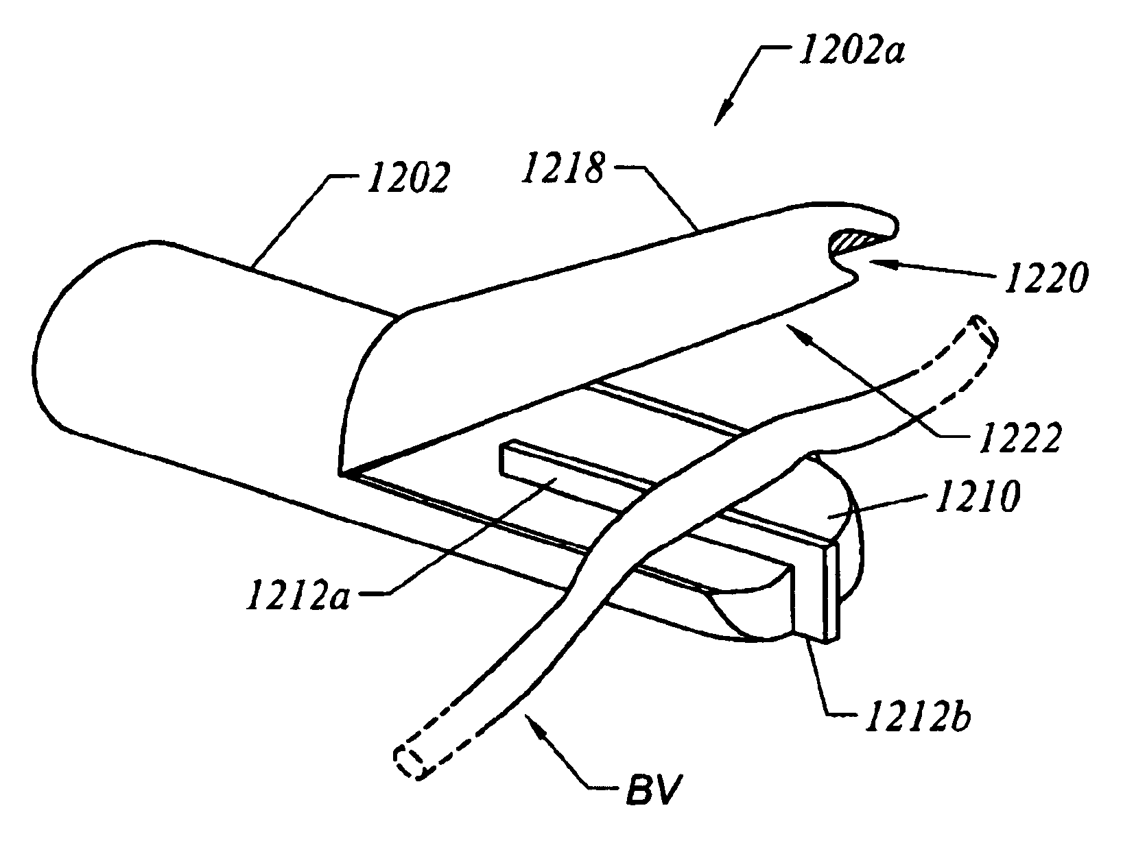
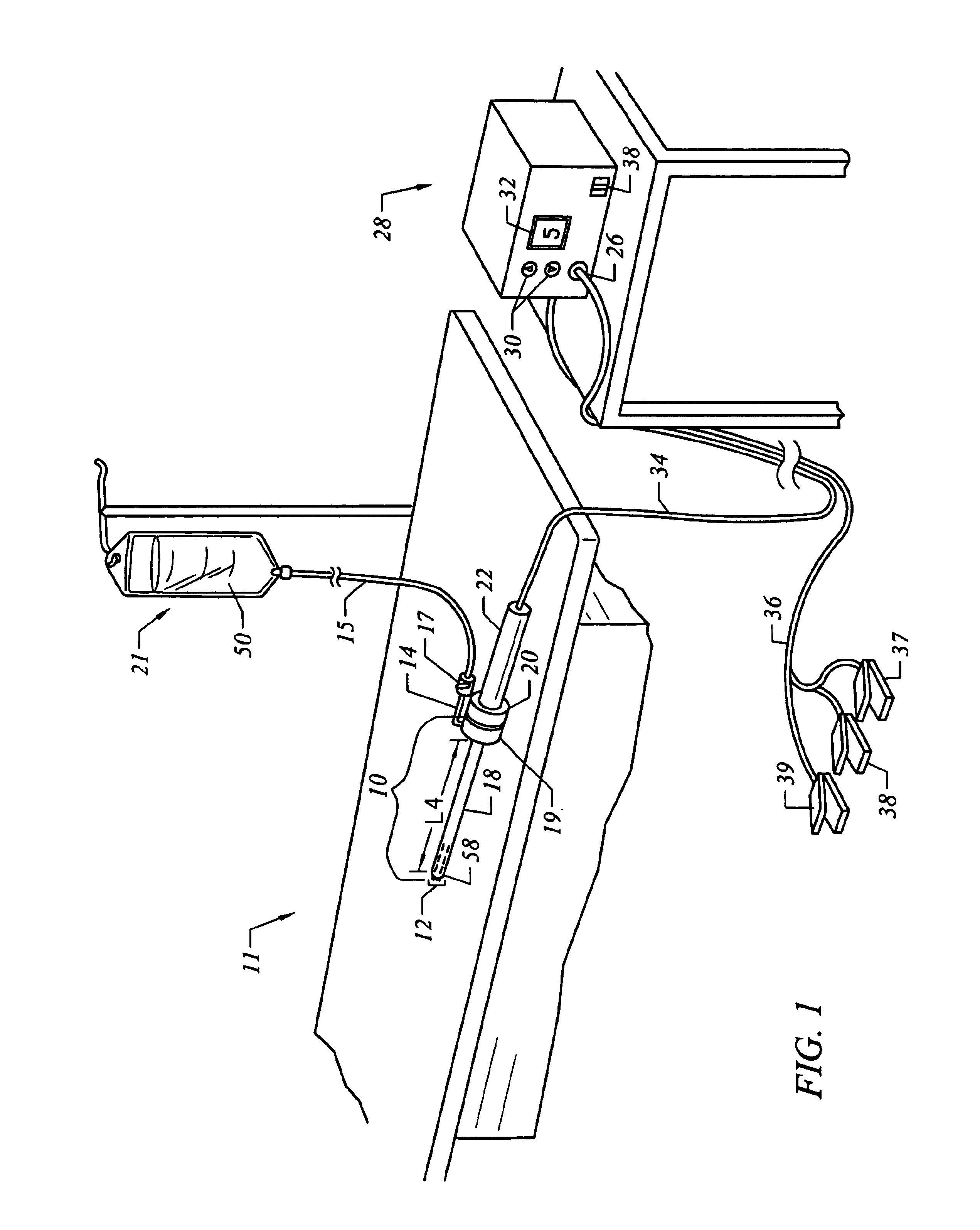
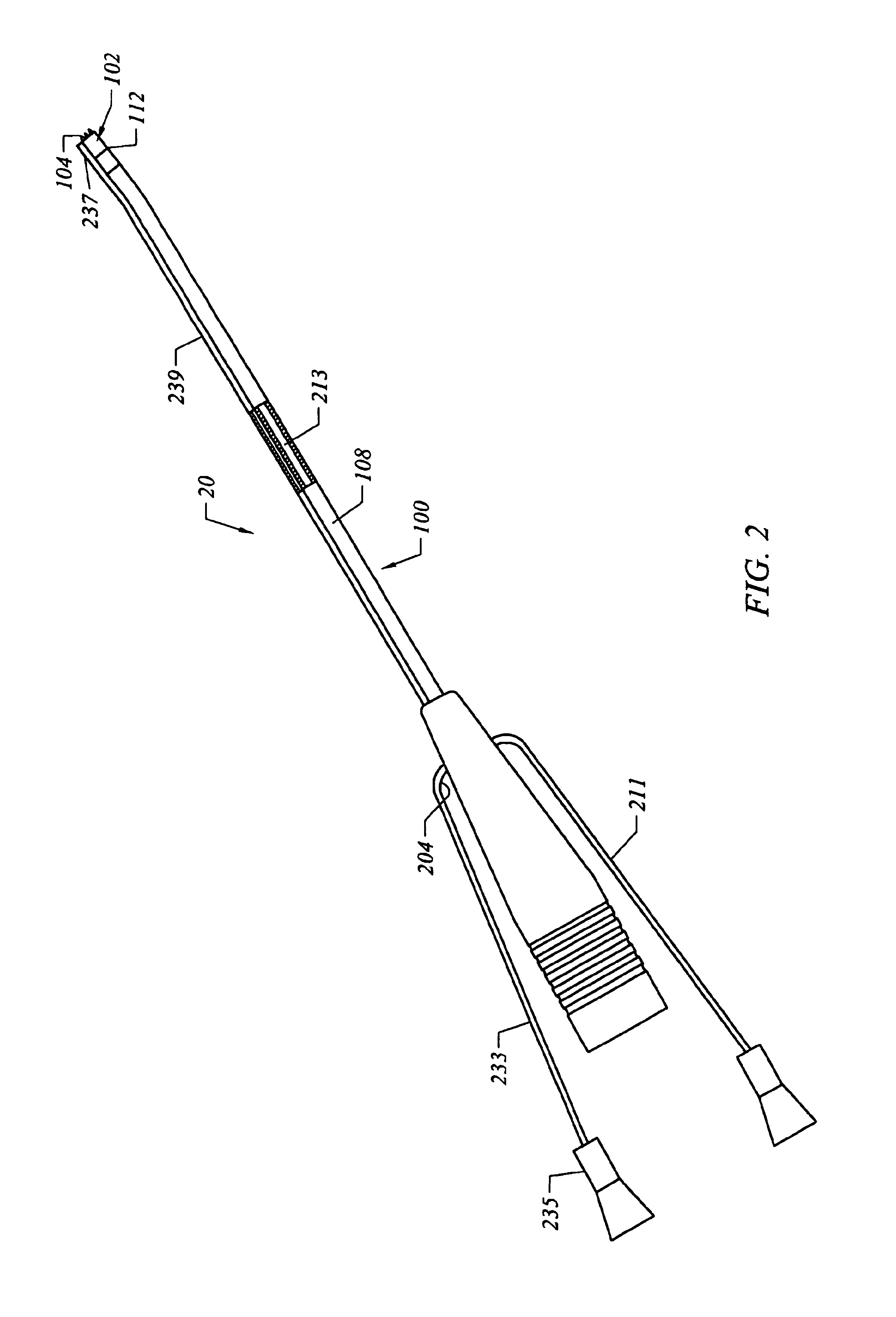
[0076]The present invention provides systems and methods for selectively applying electrical energy to a target location within or on a patient's body, particularly for cutting, ablating, clamping, and coagulating a tissue using an electrosurgical probe. The instant invention also provides apparatus and methods for making incisions to access a tissue or organ within a patient's body, to dissect or harvest the tissue or organ from the patient, and to transect, resect, or otherwise modify the tissue or organ. The present invention is useful in procedures where the target tissue or organ is, or can be, flooded or submerged with an electrically conductive fluid, such as isotonic saline. In addition, tissues which may be treated by the system and method of the present invention further include, but are not limited to, tissues of the heart, chest, knee, shoulder, ankle, hip, elbow, hand or foot; as well as prostate tissue, leiomyomas (fibroids) located within the uterus, gingival tissues ...


PUM

PropertyMeasurementUnit
Angleaaaaaaaaaa
Angleaaaaaaaaaa
Lengthaaaaaaaaaa

Abstract

The present invention provides systems, apparatus and methods for selectively applying electrical energy to body tissue in order to ablate, contract, coagulate, or otherwise modify a target tissue or organ of a patients. An electrosurgical apparatus of the invention includes a shaft having a shaft distal end bearing an active electrode and a return electrode. At least one of the active electrode and the return electrode is moveable such that the shaft distal end can adopt a closed configuration or an open configuration. The apparatus can operate in an ablation mode or a sub-ablation mode. The closed configuration is adapted for clamping and coagulating a target tissue while the apparatus is operating in the sub-ablation mode, while the open configuration is adapted for ablating the target tissue via molecular dissociation of tissue components. A method of the present invention comprises clamping a target tissue or organ with an electrosurgical probe. A first high frequency voltage is applied between the active electrode and the return electrode to effect coagulation of the clamped tissue. Thereafter, a second high frequency voltage is applied to effect localized molecular dissociation of the coagulated tissue. The present invention allows the ablation or modification of the target tissue with minimal or no damage to surrounding, non-target tissue.

Description

CROSS-REFERENCES TO RELATED APPLICATIONS[0001]The present invention is a continuation-in-part of U.S. patent application Ser. No. 09 / 780,745 filed Feb. 9, 2001 now U.S. Pat. No. 6,770,071, which claims priority from U.S. Provisional Patent Application No. 60 / 182,751 filed Feb. 16, 2000. U.S. patent application Ser. No. 09 / 780,745 filed Feb. 9, 2001 is a continuation-in-part of U.S. patent application Ser. No. 09 / 041,934, filed Mar. 13, 1998 now U.S. Pat. No. 6,391,025, which is a continuation-in-part of U.S. patent application Ser. No. 08 / 990,374, filed Dec. 15, 1997 now U.S. Pat. No. 6,109,268, which is a continuation-in-part of U.S. patent application Ser. No. 08 / 485,219 (now U.S. Pat. No. 5,697,281), filed on Jun. 7, 1995, which was a continuation-in-part of PCT International Application, U.S. National Phase Serial No. PCT / US94 / 05168 (now U.S. Pat. No. 5,697,909), filed on May 10, 1994, which was a continuation-in-part of application Ser. No. 08 / 059,681, filed on May 10, 1993 now...

Claims


Application Information

Patent Timeline
IPC IPC(8): A61B17/00A61B18/00A61B18/12A61B18/14A61F2/02A61M1/00A61M3/02
CPCA61B18/12A61B18/1206A61B18/1402A61B18/148A61B18/1482A61B18/1485A61B18/149A61B18/1492A61B2018/00083A61B2018/00119A61B2018/00148A61B2018/0016A61B2018/00178A61B2018/00327A61B2018/00392A61B2018/00404A61B2018/0047A61B2018/00476A61B2018/00505A61B2018/00577A61B2018/00583A61B2018/00601A61B2018/00625A61B2018/0066A61B2018/00678A61B2018/00702A61B2018/00726A61B2018/00791A61B2018/00797A61B2018/00815A61B2018/00821A61B2018/00827A61B2018/00875A61B2018/00982A61B2018/1213A61B2018/124A61B2018/1253A61B2018/126A61B2018/1273A61B2018/1407A61B2018/1412A61B2018/1422A61B2018/1467A61B2018/1472A61B2018/162A61B2018/165A61B2218/002A61B2218/003A61B2218/007A61F2/2493A61M3/0283A61B18/042A61B2017/00026A61B2017/00084A61B2017/00101A61B2017/00247A61B2018/00029
Inventor WOLOSZKO, JEANTSUJI, CRAIGORMSBY, THEODORE C.
Owner ARTHROCARE
Why Eureka
Try Eureka