Resistance welding electrode

a welding electrode and resistance technology, applied in the field of resistance welding electrodes, can solve the problems of poor interference fit, increased consumption of holders with relatively high manufacturing costs, and electrode parts becoming detached from the holders, etc., to achieve convenient manufacturability and reliability, improve force transmission and current transmission characteristics, and save materials.

Active Publication Date: 2017-02-14
HOLZHAUER GMBH & CO KG
View PDF14 Cites 5 Cited by
  • Summary
  • Abstract
  • Description
  • Claims
  • Application Information

AI Technical Summary

Benefits of technology

[0005]It is an object of the invention to provide a resistance welding electrode which provides a readily manufacturable and reliable interference fit between holder and electrode part with improved force transmission and current transmission characteristics, as well as to attain an economical and material-saving application of such resistance welding electrodes.

Problems solved by technology

When the electrode parts need to be exchanged, difficulties can arise, such as leaks, a poor interference fit and the risk that the electrode part becomes detached from the holder, as well as an increased consumption of holders which have relatively high manufacturing costs.
Additional cost due to lost production can also occur.

Method used


Image

  • Resistance welding electrode
  • Resistance welding electrode
  • Resistance welding electrode

Examples


Embodiment Construction

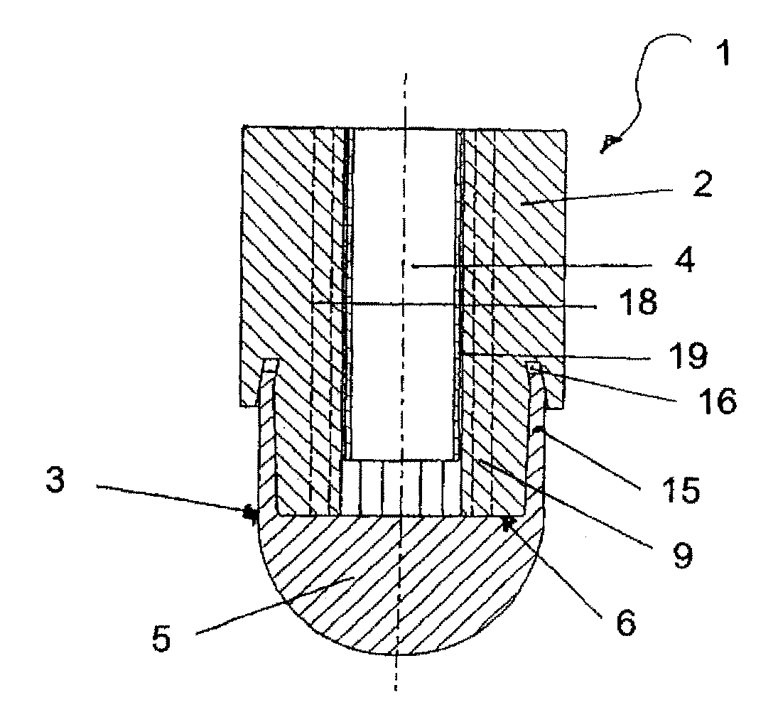
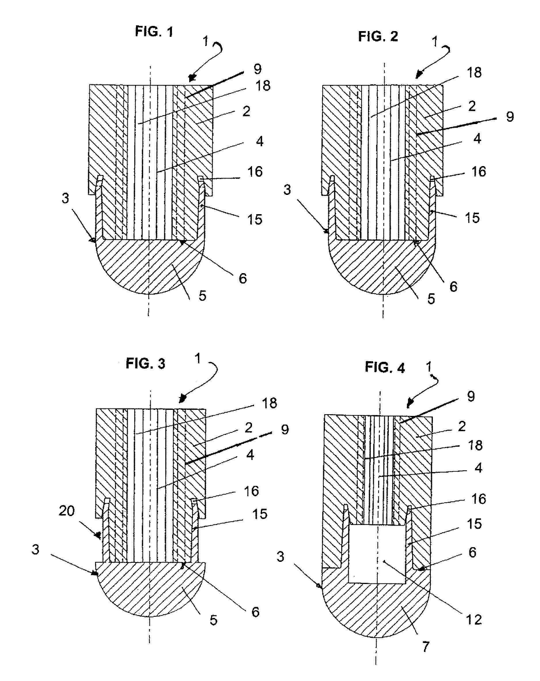
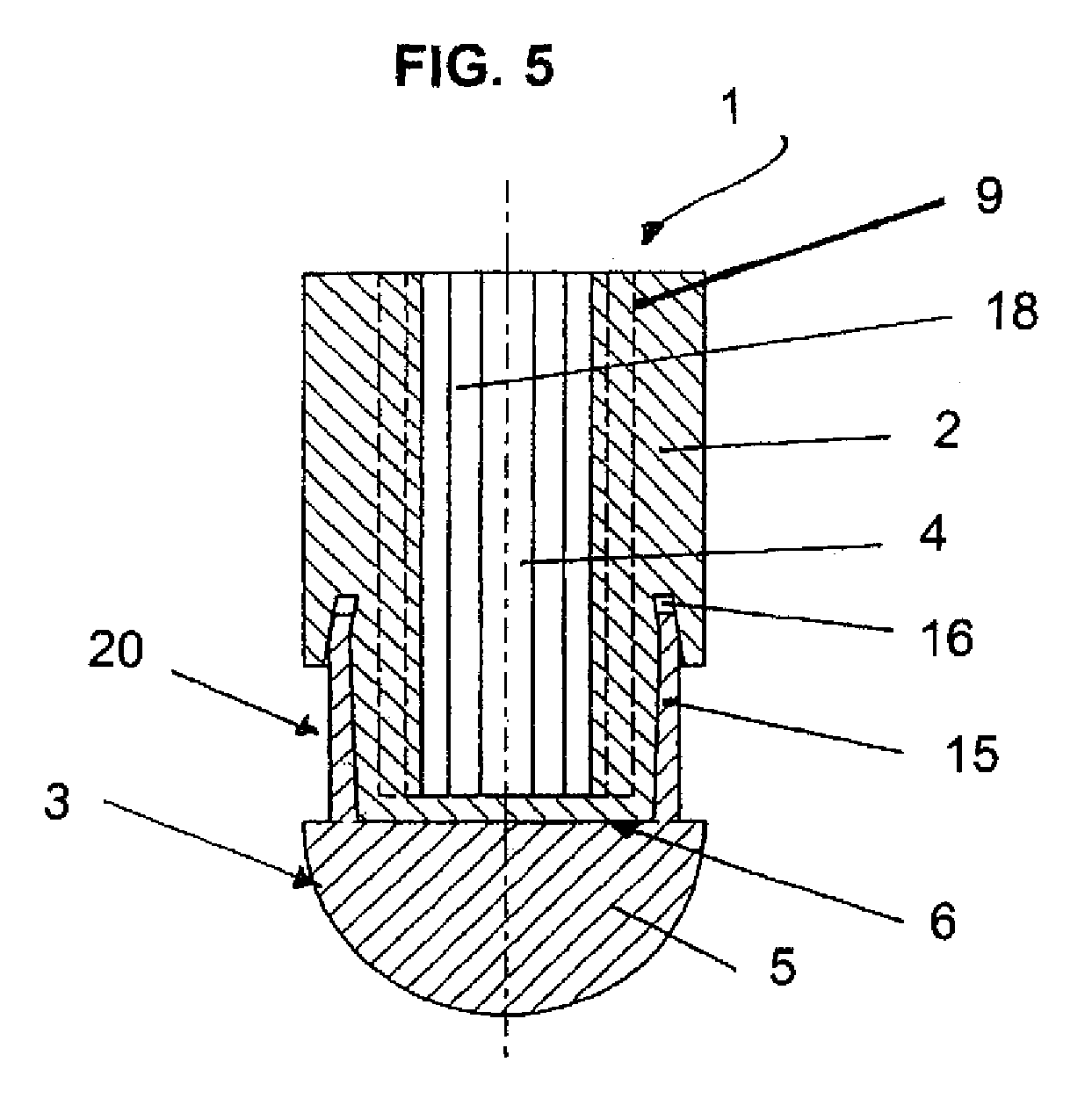
[0028]The resistance welding electrodes 1 in all embodiments of resistance welding electrodes illustrated in the Figures are indicated with the general reference symbol 1. The resistance welding electrode 1 includes a shaft-shaped holder 2 and an electrode part having the general reference symbol 3. The electrode part can be designed in form of an electrode cap 5 (female embodiment) or in form of a rod electrode 7 (male embodiment). Composites electrodes 3′ can also be provided in other described embodiments of the resistance welding electrode 1.

[0029]The respective shaft-shaped holder shown with the general reference symbol 2 has at least one cooling bore 4 which is preferably provided with cooling fins 18. The electrode cap 5 or the rod electrode 7 is connected with the shaft-shaped holder 2 via conical surfaces. These conical surfaces have a cone angle ranging from about 1° to about 3°. Moreover, the holder 2 and the electrode part 3 and / or 3′ are joined such that the holder 2 an...


PUM

PropertyMeasurementUnit
cone angleaaaaaaaaaa

Abstract

A resistance welding electrode includes a shaft-shaped holder and an electrode part in the form of an electrode cap or a pin electrode which are non-positively connected via tapered surfaces. Furthermore, cooling bores are also present. In such a resistance welding electrode the tapered cone angle is in a region of about 1 degree to 3 degrees and the holder and the electrode part are connected such that the holder and the electrode part are further in axial contact with each other via a radial surface contact, and the edge of the electrode part facing the holder is restrained in an associated reception recess on the holder side by means of reduction.

Description

CROSS-REFERENCES TO RELATED APPLICATIONS[0001]This application is the U.S. National Stage of International Application No. PCT / EP2009 / 007107, filed Oct. 5, 2009, which designated the United States and has been published as International Publication No. WO 2010 / 040488 and which claims the priority of German Patent Applications, Serial No. 10 2008 050 567.6, filed Oct. 6, 2008, and Serial No. 10 2009 047 920.1, filed Oct. 1, 2009, pursuant to 35 U.S.C. 119(a)-(d).BACKGROUND OF THE INVENTION[0002]The invention relates to a resistance welding electrode, which has a shaft-shaped holder and an electrode part. The electrode part can be constructed in form of an electrode cap (female) or a rod electrode (male). The respective electrode part is non-positively connected with the associated holder via matching conical surfaces. Optionally, a cooling bore can be provided for a high-performance application.[0003]In conventional welding electrodes of this type, a cone angle of 4 to 7 degrees is u...

Claims


Application Information

Patent Timeline
Patent Type & Authority Patents(United States)
IPC IPC(8): B23K11/30
CPCB23K11/3018B23K11/30
Inventor HOLZHAUER, ANTON
Owner HOLZHAUER GMBH & CO KG
Why Eureka
Try Eureka