
Christmas rotating ornament

a rotating ornament and ornament technology, applied in the field offestive atmosphere decorative lighting devices, can solve the problems of general limitation to a single device, limited display types of devices involved, and room for improvemen

Active Publication Date: 2017-03-07
NATURES MARK LLC
View PDF16 Cites 11 Cited by
  • Summary
  • Abstract
  • Description
  • Claims
  • Application Information

AI Technical Summary

Benefits of technology

[0012]It is an object of the present invention to provide an improved atmospheric lighting device which will provide special decorative effects which involve rich forms of expression.
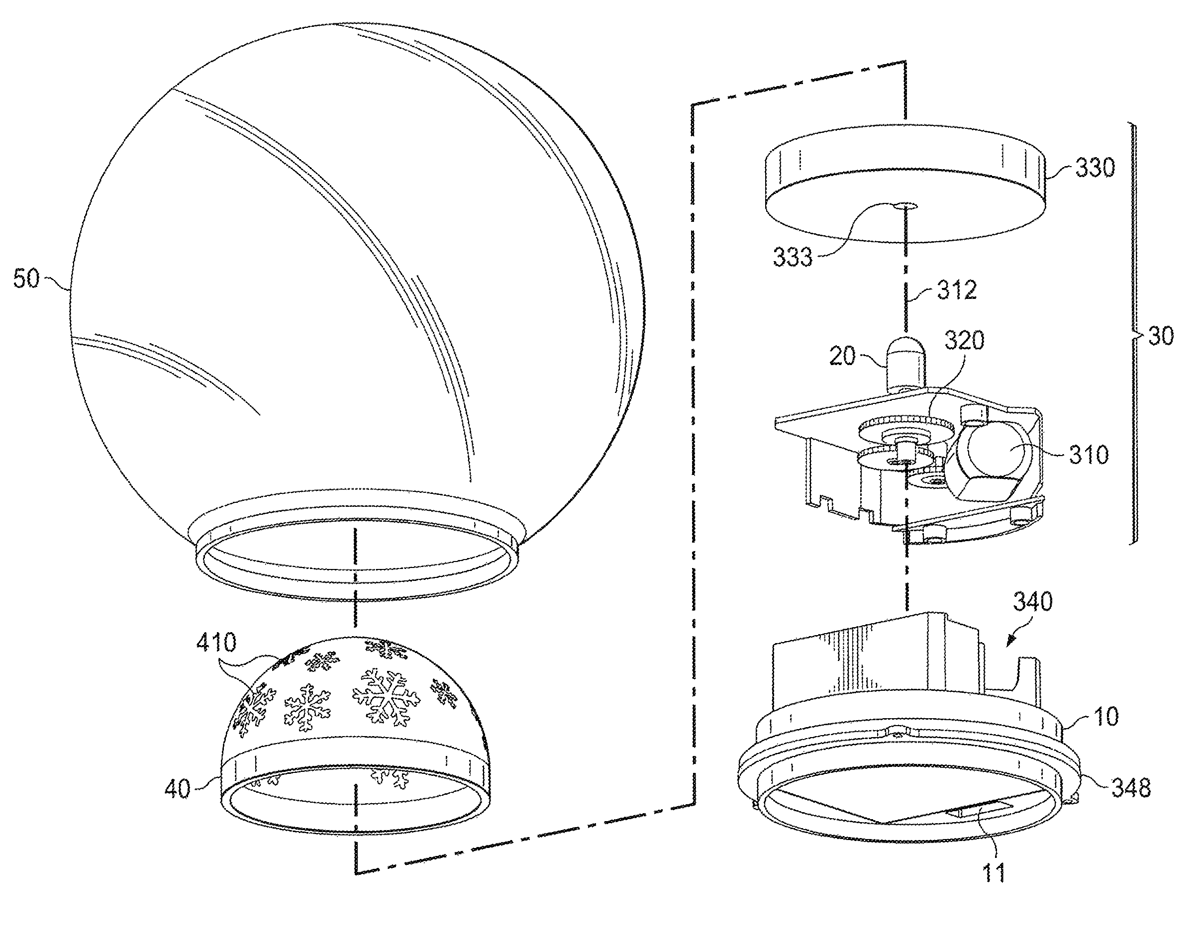
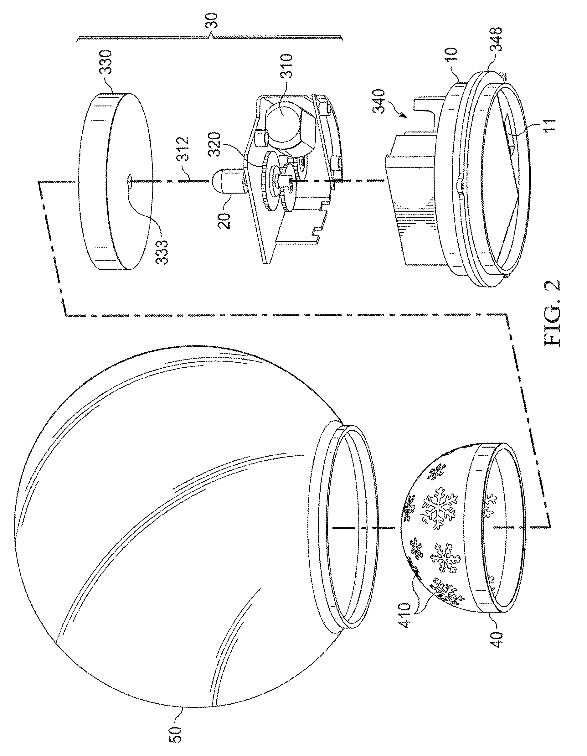
[0021]As has been described, the inner cover is located between the LED bulb and the transparent lamp shade. In use, by control of the switch assembly, the LED bulb is energized and emits light. The spinning configuration starts to drive the inner cover, causing it to spin, and accordingly the cutout inner cover spins with respect to the LED bulb, so as to enable the emitting light going through the cutout patterned holes to present a flowing vivid silhouette, which is a very pleasing visual expression as a decorative lighting effect.

Problems solved by technology

Since these prior art decorative lighting devices have generally involved patterns on a lamp shade or on a bulb, they were generally limited to a single expression of the shadow projection.
Other devices involved the use of a glass or plastic globe, but again the devices were limited in the types of displays they involved.
While certainly decorative, these devices leave room for improvement in enhancing the decorative effects of atmospheric lighting products.

Method used


Image

  • Christmas rotating ornament
  • Christmas rotating ornament
  • Christmas rotating ornament

Examples


Embodiment Construction

[0028]In order to further describe the purpose of the present invention, the technical solution and advantages more clearly, the disclosure incorporates the accompanying drawings as well as the detailed description which follows. It should be understood, however, that the preferred embodiments described herein are merely for the better understanding of the present invention and the technical solution, and should not be used to limit the present invention.

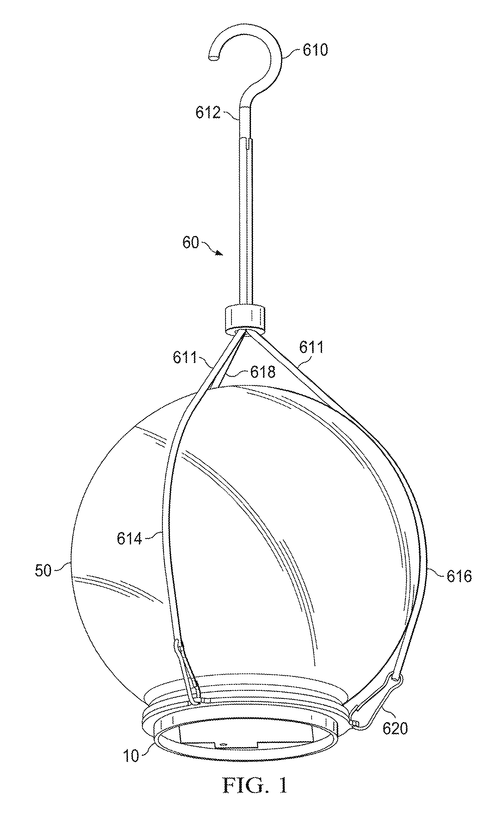
[0029]FIGS. 1 and 2 depict the festive atmosphere decorative lighting device of the invention. As has been briefly described, the lighting device of the invention in one preferred form includes: a lamp base 10 and an LED bulb set (such as 20 in FIG. 2) inside the lamp base 10 which is operably controlled by a switch assembly. The switch assembly can be any of a number of conveniently available simple electromechanical devices with two sets of electrical contacts which are connected to external circuits. The contacts are either “clos...


PUM

PropertyMeasurementUnit
transparentaaaaaaaaaa
rotationaaaaaaaaaa
thicknessaaaaaaaaaa

Abstract

A festive atmosphere decorative lighting device which includes a lamp base, an LED bulb set inside the lamp base and an electrical switch for the bulb. A spinning assembly housed in the lamp base has an output shaft which is connected to an inner cover for spinning the inner cover. The inner cover fits over the LED bulb and has a cutout pattern of holes. The lamp base is also fitted with a transparent lamp shade which is superimposed above the inner cover. When the LED bulb is switched on and the spinning configuration spins the inner cover, light emitted by the LED bulb passes through the holes in the inner cover and presents a flowing vivid silhouette, as observed by a viewer.

Description

CROSS REFERENCE TO RELATED APPLICATION[0001]The present application claims priority from an earlier filed Chinese utility patent application entitled “Christmas Rotating Ornament”, Serial No. 201510478041.6, filed Aug. 7, 2015, by the same inventor.BACKGROUND OF THE INVENTION[0002]Field of the Invention[0003]The present invention relates to a lighting fixture, and more particularly to a kind of festive atmosphere decorative lighting device.[0004]Description of the Prior Art[0005]Christmas holidays, as well as other festive occasions, often involve the use of atmospheric lighting devices in order to increase the festival atmosphere. Other than the general lighting fixtures, there have also been various special purpose atmospheric decorative lighting products known in the past to provide this type of decorative effect. One such known device accomplishes the decorative effect by illuminating a static body, for example, through patterns on a lamp shade or on a bulb associated with the d...

Claims


Application Information

Patent Timeline
Patent Type & Authority Patents(United States)
IPC IPC(8): F21V23/04F21V17/00F21V3/04F21V21/08F21V14/08F21V3/02F21W121/00
CPCF21V3/02F21V3/0427F21V17/002F21V21/08F21V23/0442F21V14/08F21W2121/00F21Y2101/00F21V3/10F21S10/00F21V3/00F21V3/049F21V14/00F21V17/10F21V19/00F21V21/104F21V23/04F21S8/063F21V21/0832F21S10/063F21Y2115/10
Inventor LIU, CONGGANG
Owner NATURES MARK LLC
Learn More