Liquid ejecting device and method of manufacturing liquid ejecting device

a technology of liquid ejecting device and liquid ejecting device, which is applied in the direction of printing, etc., can solve the problems of low resin content, low endurance of protruding parts, and possible chipping of parts of protruding parts

Active Publication Date: 2017-05-02
BROTHER KOGYO KK
View PDF10 Cites 0 Cited by
  • Summary
  • Abstract
  • Description
  • Claims
  • Application Information

AI Technical Summary

Benefits of technology

[0006]In the inkjet head as described above, typically, an ink-repellent coat is formed on an ink ejection surface, which is a surface of the nozzle plate and formed with the multiple ink ejection openings, of the plastic nozzle plate at portions surrounding ejection openings of the multiple nozzles in order to prevent the ink resides around the multiple nozzles. Further, according to a conventional inkjet head, two lines of elongated protrusions, which extend in a direction of a nozzle array, are formed on the ink ejection surface of the nozzle plate with each nozzle array arranged therebetween. With the protrusions, when a printing sheet is lifted due to sheet jam or the like during a printing operation, the printing sheet is prevented or suppressed from contacting the ejection openings as it contacts the protrusions. Thus, with this configuration, a peripheral part of each ejection opening or the ink-repellent coat around each ejection opening is prevented from being damaged by the printing sheet.
[0009]Further, the protruded parts are typically formed to the plastic substrate, which is to be used as the nozzle plate, by the heat press procedure, due to the heat applied thereto during the heat press procedure, the substrate may warp at the time of the heat press procedure. In order to suppress the degree of the warp, it becomes difficult to apply a relatively large deformation to the substrate, which results in relatively low protruded parts. When the height of the protruded parts is low, the printing sheet may contact the ejection openings easily, and thus, protecting effect of the protruded parts is lowered.
[0010]In consideration of the above, according to aspects of the disclosures, an improved liquid ejecting device is provided. With the improved liquid ejecting device, protruded parts are formed in the vicinity of the ejection openings so that portions surrounding the ejection openings can be well protected from being hit by the printing sheet. Further, the protruded parts exhibit high endurance.

Problems solved by technology

Since the synthetic-resin is low, the protruded parts have low endurance.
If the printing sheet hits the protruded parts with a relatively strong force, a part of the protruded part may be chipped.
Further, the protruded parts are typically formed to the plastic substrate, which is to be used as the nozzle plate, by the heat press procedure, due to the heat applied thereto during the heat press procedure, the substrate may warp at the time of the heat press procedure.
In order to suppress the degree of the warp, it becomes difficult to apply a relatively large deformation to the substrate, which results in relatively low protruded parts.

Method used


Image

  • Liquid ejecting device and method of manufacturing liquid ejecting device
  • Liquid ejecting device and method of manufacturing liquid ejecting device
  • Liquid ejecting device and method of manufacturing liquid ejecting device

Examples


Embodiment Construction

[0023]Referring to the accompanying drawings, an illustrative embodiment and its modifications will be described. In the embodiments, an invention of a liquid ejecting device will be applied to an inkjet head.

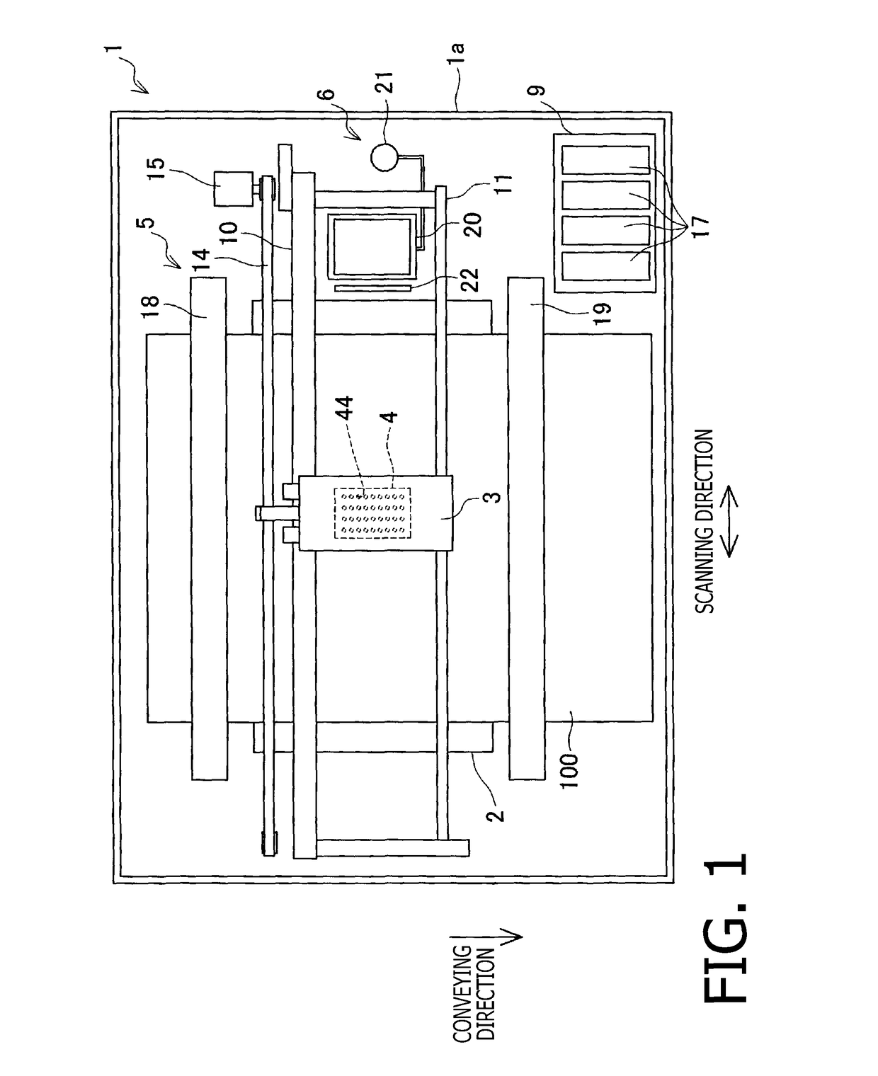
[0024]FIG. 1 schematically shows a plan view of an inkjet printer 1 according to an illustrative embodiment of the disclosures. In the following description, directions with respect to the inkjet printer 1 are defined such that a direction closer with respect to plane of FIG. 1 is an upper direction of the inkjet printer 1, while a direction farther with respect to the plane of FIG. 1 is a lower direction of the inkjet printer 1, the description will be made using the “upper” and “lower” directions with respect to the inkjet printer 1.

[0025]As shown in FIG. 1, the inkjet printer 1 has a platen 2, a carriage 3, an inkjet head 4, a conveying mechanism 5, and a maintenance mechanism 6.

[0026]A printing sheet 100 on which an image will be printed is to be placed on an upper surface ...


PUM


Abstract

A liquid ejecting device, having a fluid passage structure formed with multiple nozzles arranged in a particular nozzle arrangement direction and multiple passages respectively communicating with the multiple nozzles. The fluid passage structure has a metallic nozzle plate formed with the multiple nozzles which is arranged in a nozzle arrangement direction. Further, the metallic nozzle plate has a liquid ejection surface on which multiple ejection openings respectively corresponding to the multiple nozzles being formed, multiple convex parts protruding from the liquid ejection surface, the multiple convex parts being arranged along the nozzle arrangement direction, beside the multiple ejection openings, respectively. Further, the multiple convex parts are formed by press working applied to the nozzle plate from a side opposite to the liquid ejection surface.

Description

CROSS-REFERENCE TO RELATED APPLICATION[0001]This application claims priority under 35 U.S.C. §119 from Japanese Patent Applications No. 2014-169365 filed on Aug. 22, 2014. The entire subject matter of the application is incorporated herein by reference.BACKGROUND[0002]Technical Field[0003]The present disclosures relate to a liquid ejecting device and a method of manufacturing a liquid ejecting device.[0004]Related Art[0005]Conventionally, a liquid ejecting device has been known. An example of such a liquid ejecting device is employed in an inkjet head of an inkjet printer configured to eject ink drops through nozzles formed on the inkjet head. Typically, the inkjet head has a nozzle plate made of synthetic resin (hereinafter, occasionally referred to as plastic) and formed with multiple nozzles, a passage-formed plate made of metal and formed with inflow passages communicating with the multiple nozzles, and piezoelectric elements provided to the passage-formed plate. Such an inkjet ...

Claims


Application Information

Patent Timeline
Patent Type & Authority Patents(United States)
IPC IPC(8): B41J2/14B41J2/16B41J2/055
CPCB41J2/1632B41J2/055B41J2/14233B41J2/161B41J2/1623B41J2/1626B41J2/1634B41J2002/14266B41J2002/14419B41J2002/14459
Inventor KOIDE, SHOHEIITO, ATSUSHINAKAMOTO, HIKARUHIRAIDE, HIROAKI
Owner BROTHER KOGYO KK
Why Eureka
Try Eureka