
Clad metal ice cube tray

a metal ice cube and forming tray technology, which is applied in the field of clad metal ice forming tray, can solve the problems of slow plastic twist trays, unreliable, and large energy consumption of conventional die cast trays with heaters and harvesters

Active Publication Date: 2017-05-02
WHIRLPOOL CORP
View PDF9 Cites 0 Cited by
  • Summary
  • Abstract
  • Description
  • Claims
  • Application Information

AI Technical Summary

Benefits of technology

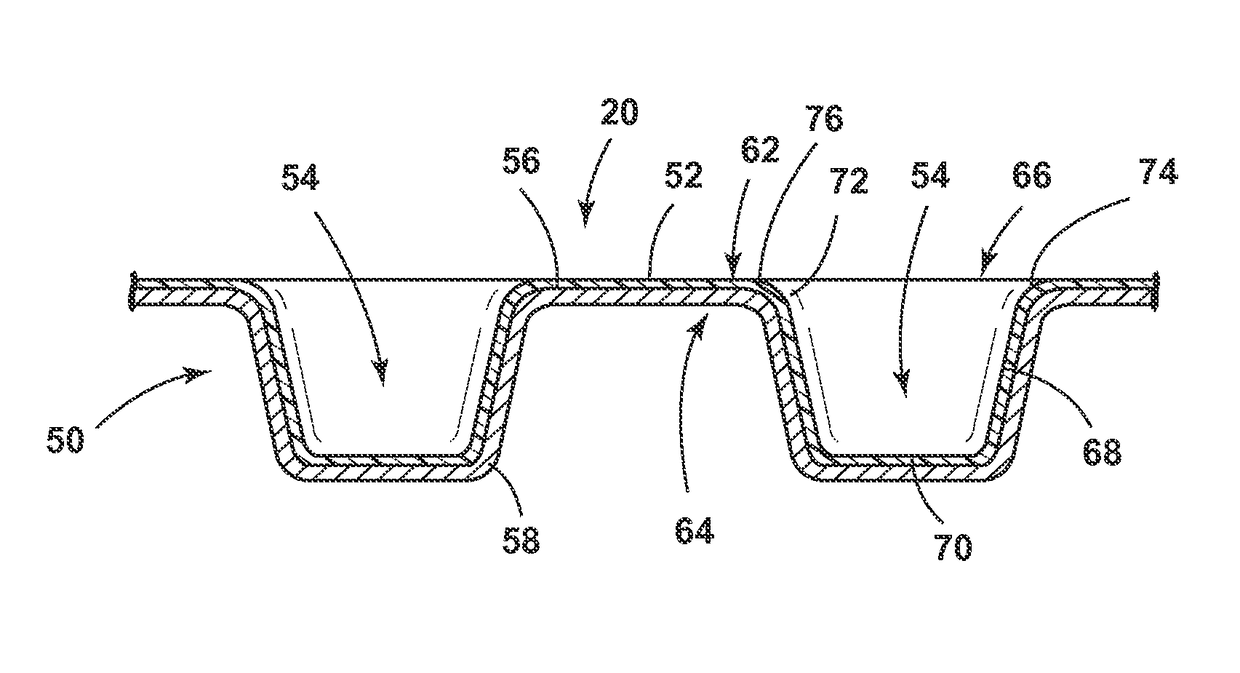
[0003]Another aspect of the present invention is a method of releasing ice from a clad metal ice forming tray assembly for a refrigerator. The method includes the steps of providing a clad metal ice forming tray comprising a clad metal having at least a first alloy sheet and a second alloy sheet different from the first and having different coefficients of thermal expansion and at least one ice recess stamped in the clad bi-metal, defined along its bottom by a bottom surface and its sides by at least one wall extending upwardly from the bottom surface, wherein the bottom surface and the at least one wall comprise the clad bi-metal, wherein each of the bottom surface and the at least one walls comprises an interior surface which is facing the ice recess and an exterior surface which is facing away from the ice recess; providing ice in the at least one ice recess; creating shear stress between the ice forming tray and the ice by modifying the temperature of the ice forming tray or applying electrical resistive heating such that one of the first or second alloy sheets expands due to its coefficient of thermal expansion. The expansion causes the ice forming tray to release the ice.

Problems solved by technology

Additionally, conventional die cast trays with heaters and harvesters use a large amount of energy, and plastic twist trays can be slow and unreliable.

Method used


Image

  • Clad metal ice cube tray
  • Clad metal ice cube tray
  • Clad metal ice cube tray

Examples


Embodiment Construction

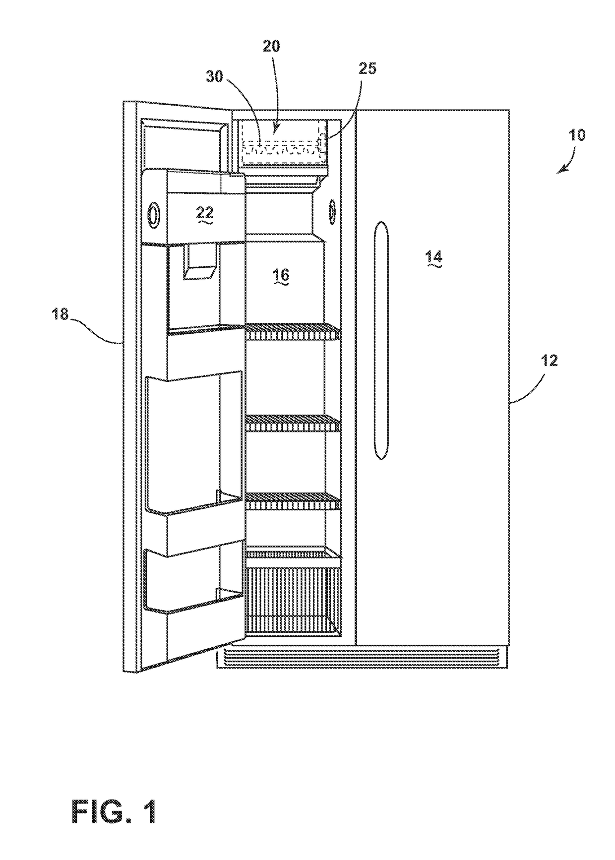
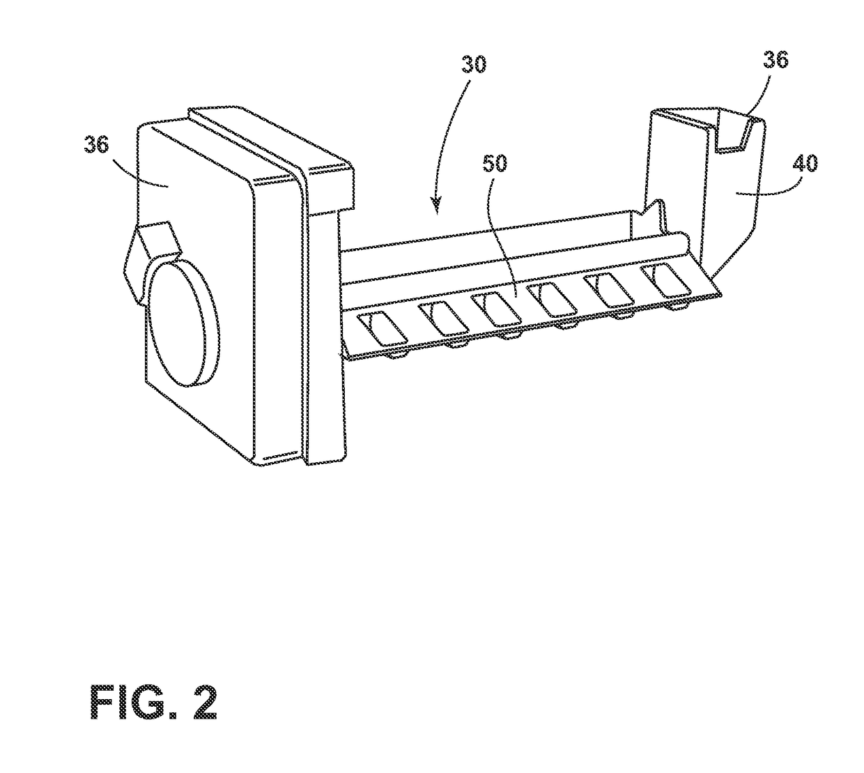
[0011]In FIG. 1, a refrigerator 10 includes a fresh food compartment 12, a fresh food compartment door 14, a freezer compartment 16, and freezer compartment door 18. Freezer compartment door 18 is shown in an open position in FIG. 1, revealing an automatic ice maker 20 and ice piece collection receptacle 22. Also, FIG. 1 shows the refrigerator as a side-by-side configuration, but it should be understood that a refrigerator may be any configuration, such as a French door bottom-mount freezer or top mount freezer configuration. The ice maker 20 includes a housing 25. Located within the housing 25 is an ice-making assembly 30. It should be understood that the ice maker 20 and ice-making assembly 30 can be configured in various locations within refrigerator 10, including within the freezer compartment 16, fresh food compartment 12, fresh food compartment door 14, and freezer door 18. Also, the automatic ice maker 20 and ice making assembly 30 may be used within any freezer environment, ...


PUM

PropertyMeasurementUnit
thicknessaaaaaaaaaa
thicknessaaaaaaaaaa
angleaaaaaaaaaa

Abstract

A clad metal ice forming tray assembly for a refrigerator is disclosed. The ice forming tray includes a clad metal comprised of at least a first alloy sheet and a second alloy sheet different from the first and having different coefficients of thermal expansion. The tray also includes ice recesses stamped in the clad bi-metal.

Description

BACKGROUND OF THE INVENTION[0001]Various types of trays have been developed for forming ice cubes. Many modern refrigerator appliances possess automatic ice-making capabilities. Although these ice makers are highly desirable, they have some distinct disadvantages. Automatic dispensing ice cube trays require heat and / or mechanical action to release the ice. Additionally, conventional die cast trays with heaters and harvesters use a large amount of energy, and plastic twist trays can be slow and unreliable.BRIEF DESCRIPTION OF THE INVENTION[0002]One aspect of the present invention includes a clad metal ice forming tray assembly for a refrigerator. The ice forming tray comprises a clad metal having at least a first alloy sheet and a second alloy sheet different from the first and having different coefficients of thermal expansion; and an ice recess stamped in the clad bi-metal, defined along its bottom by a bottom surface and its sides by at least one wall extending upwardly from the b...

Claims


Application Information

Patent Timeline
Patent Type & Authority Patents(United States)
IPC IPC(8): F25C1/22F25C1/24F25C5/06F25C5/08F25C5/02C22C38/40C22C38/08
CPCF25C5/08F25C1/24F25C5/06C22C38/08C22C38/40F25C2400/02
Inventor CRAVENS, CHARLES R.
Owner WHIRLPOOL CORP
Learn More