
Monitoring a region of interest in a subsurface formation

a subsurface formation and monitoring technology, applied in the direction of instruments, analogue processes for specific applications, electric/magnetic computing, etc., can solve the problems of two-way travel time, seismic velocity change in seismic parameter, and more difficult and less developed

Inactive Publication Date: 2011-02-24
SHELL OIL CO
View PDF3 Cites 18 Cited by
  • Summary
  • Abstract
  • Description
  • Claims
  • Application Information

AI Technical Summary

Benefits of technology

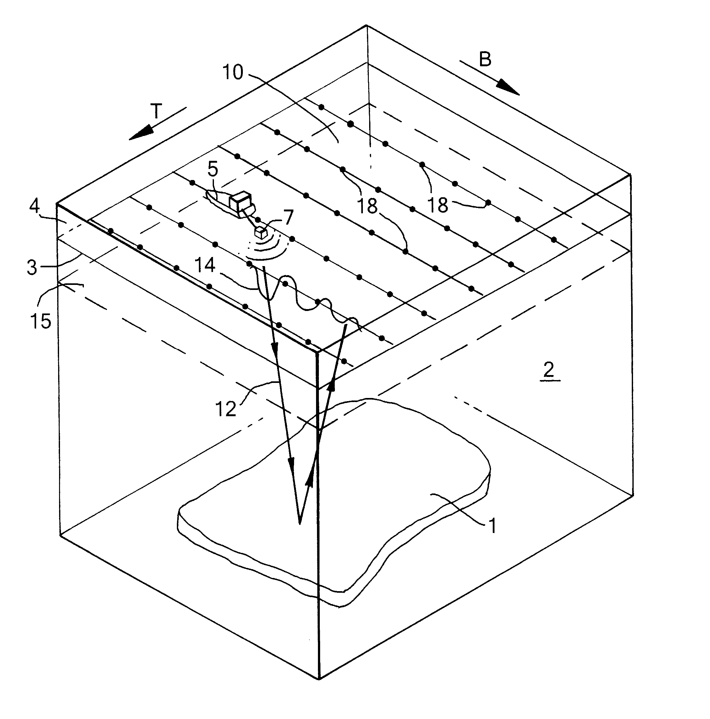
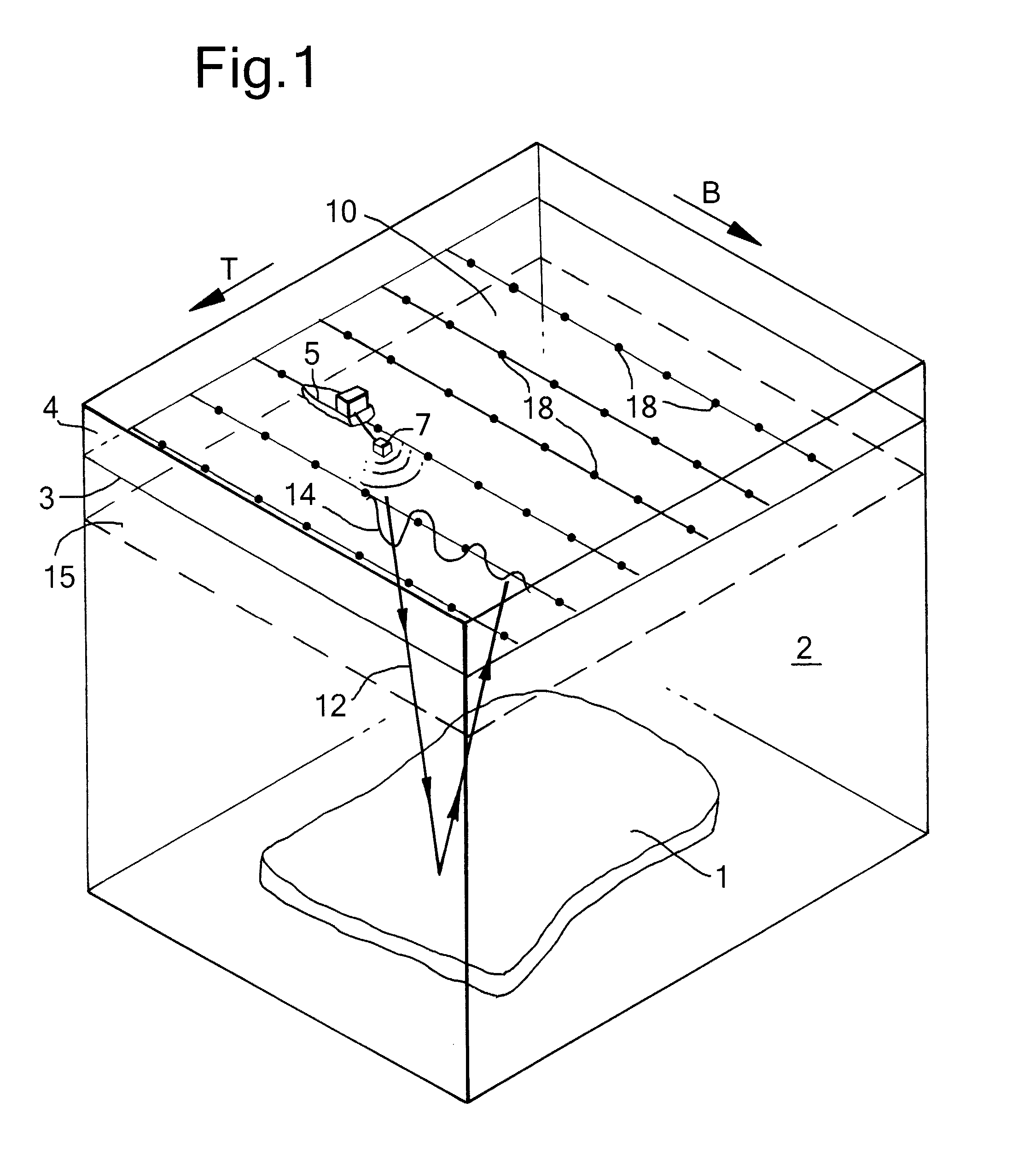
[0029]The method is applied with advantage when the subsurface formation comprises a reservoir region, for example a hydrocarbon reservoir, and wherein the volume change takes place in the course of production of a fluid from or injection of a fluid into the fluid reservoir, or in the course of modifying the temperature of the reservoir region.

Problems solved by technology

More difficult and less developed are methods that allow monitoring of the compaction of the depleting reservoir region in the course of production.
Stress changes cause changes in the seismic parameter seismic velocity, and therefore also in two-way travel time.
A general difficulty in seismic surveying of oil or gas fields is that the reservoir region normally lies several hundreds of meters up to several thousands of meters below the earth's surface, but the thickness of the reservoir region or layer is comparatively small, i.e. typically only several meters or tens of meters.
Sensitivity to detect small changes in the reservoir region is therefore an issue.
Due to the depth, phenomena intermediate between the earth's surface and the reservoir can hamper the analysis, such as the presence of a gas cloud above the reservoir.

Method used


Image

  • Monitoring a region of interest in a subsurface formation
  • Monitoring a region of interest in a subsurface formation
  • Monitoring a region of interest in a subsurface formation

Examples


Embodiment Construction

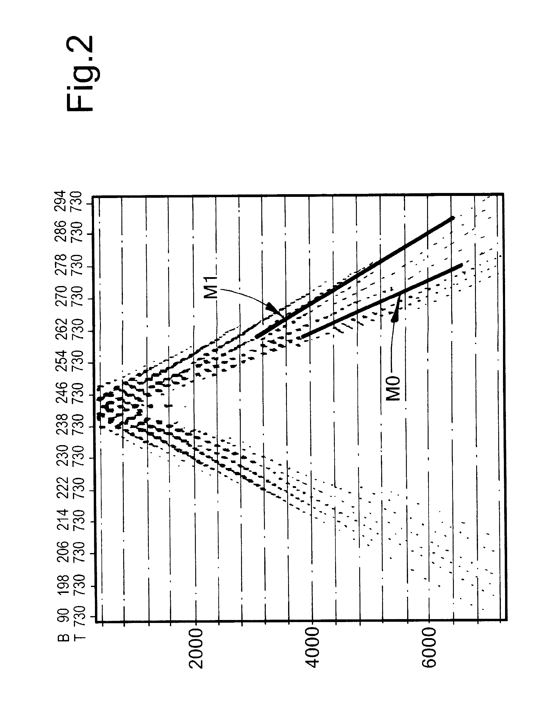
[0040]Although surface waves are typically generated along with body waves in conventional seismic surveying, they are not often processed and interpreted. The paper “Scholte wave velocity inversion for a near surface S-velocity model and PS-statics” by E. Muyzert; Soc. of Expl. Geophys.; 70th Ann. Internat. Mtg. 2000, p. 1197-1200, incorporated herein by reference, discusses fundamental aspects of Scholte waves such as frequency dependence, depth penetration, and fundamental and higher modes, and discloses a method for constructing a S-velocity model of the shallow seabed that laterally varies along one horizontal dimension, using Scholte waves.

[0041]The paper “Multichannel analysis of surface waves (MASW)- active and passive methods” by C. B. Park et al., The Leading Edge, January 2007, p. 60-64, discusses the frequency-dispersion analysis of land surface waves to investigate shallow soil layers, for geotechnical application, such as construction sites, with a maximum depth of 30 ...


PUM


Abstract

A method of monitoring a subsurface formation (2) including a region of interest (1), below a surface region, which method comprises the steps of exciting seismic interface waves (14), in the surface region over an area of the earth's surface at a first and a second moment in time; detecting seismic interface waves signals for a plurality of locations in the area; determining, from the detected seismic interface wave signals, an areal distribution of a parameter related to seismic interface wave velocity change between the first and second moments in time; and inferring, from the areal distribution, an indication of a volume change of the region of interest between the first and second moments in time.

Description

[0001]The present invention relates to a method of monitoring a region of interest in a subsurface formation, which region of interest undergoes a volume change. The region of interest can in particular be a reservoir region, and the volume change can be caused by withdrawal of a fluid from or injection of a fluid into the reservoir region, or by a changing the temperature of the reservoir region.BACKGROUND OF THE INVENTION[0002]There is a need for technologies that allow monitoring of depleting reservoir regions during production of hydrocarbons (oil and / or natural gas) from the reservoir. The geometric structure of a reservoir region in a subsurface formation is normally explored by geophysical methods, in particular seismic imaging of the subsurface during the exploration stage of an oil field. More difficult and less developed are methods that allow monitoring of the compaction of the depleting reservoir region in the course of production. One approach is to study the deformatio...

Claims


Application Information

Patent Timeline
Patent Type & Authority Applications(United States)
IPC IPC(8): G06G7/57G06G7/48
CPCG01V1/30G01V1/303
Inventor HATCHELL, PAUL JAMESWILLS, PETER BERKELEY
Owner SHELL OIL CO
Learn More