Portable container system for heating a beverage

a beverage and container technology, applied in the field of beverage container systems, can solve the problems of difficult heating to a desired temperature on a consistent basis, undesirable wait time for heating beverages, etc., and achieve the effect of precise temperature and quick heating

Active Publication Date: 2017-05-02
RAYOVAC CORP
View PDF84 Cites 8 Cited by
  • Summary
  • Abstract
  • Description
  • Claims
  • Application Information

AI Technical Summary

Problems solved by technology

In portable container systems for heating a beverage, the wait time for heating the beverage can often be undesirable.
Heating to a desired temperature on a consistent basis is also a challenge.

Method used


Image

  • Portable container system for heating a beverage
  • Portable container system for heating a beverage
  • Portable container system for heating a beverage

Examples


second embodiment

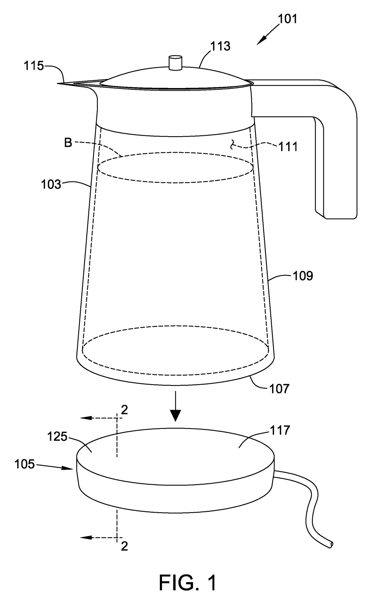
[0028]FIGS. 3 and 4 illustrate a portable container system 201 for heating a beverage B. In this embodiment, the container system 201 comprises a container 203 and thin film heating element 219 that are held in assembly so that the heating element remains with the container during heating, transport and dispensing. The container 203 is in some respects similar to the container103 of FIG. 1 in that it includes a bottom 207 and a side wall 209. While the container 203 is of generally the same shape as that of the container 103 of FIG. 1, it is understood that it may have any of the shapes described previously herein and remain within the scope of this invention. A base 231 of the container 203 is attached to the bottom 207 of the container and more suitably in part defines the bottom of the container.

first embodiment

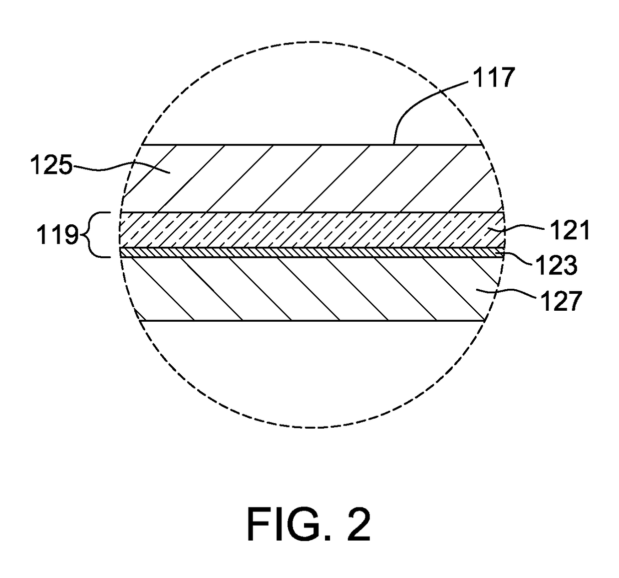
[0029]For example, in one embodiment, illustrated in FIG. 4, the base 231 of the container 203 is comprised of multiple layers including the thin film heating element 219. As in the first embodiment, the thin film heating element 219 comprises a substrate 221 and a thin film layer 223 of electrically conductive material. The base 231 also includes a top barrier layer 225 and a bottom barrier layer 227 between which the thin film heating element 219 is sandwiched.

[0030]A suitable controller (not shown) may comprise a Strix electrical controller to allow for “cordless” connection and control. It is also appreciated that the controller may regulate the amount of heat that is generated by the thin film heating element 219. For example, in one embodiment operation of the heating element 219 may be controlled by switching the system on and allowing the heating element 219 to operate until the contents of the container boil or reach a desired temperature, at which time the heating element ...

third embodiment

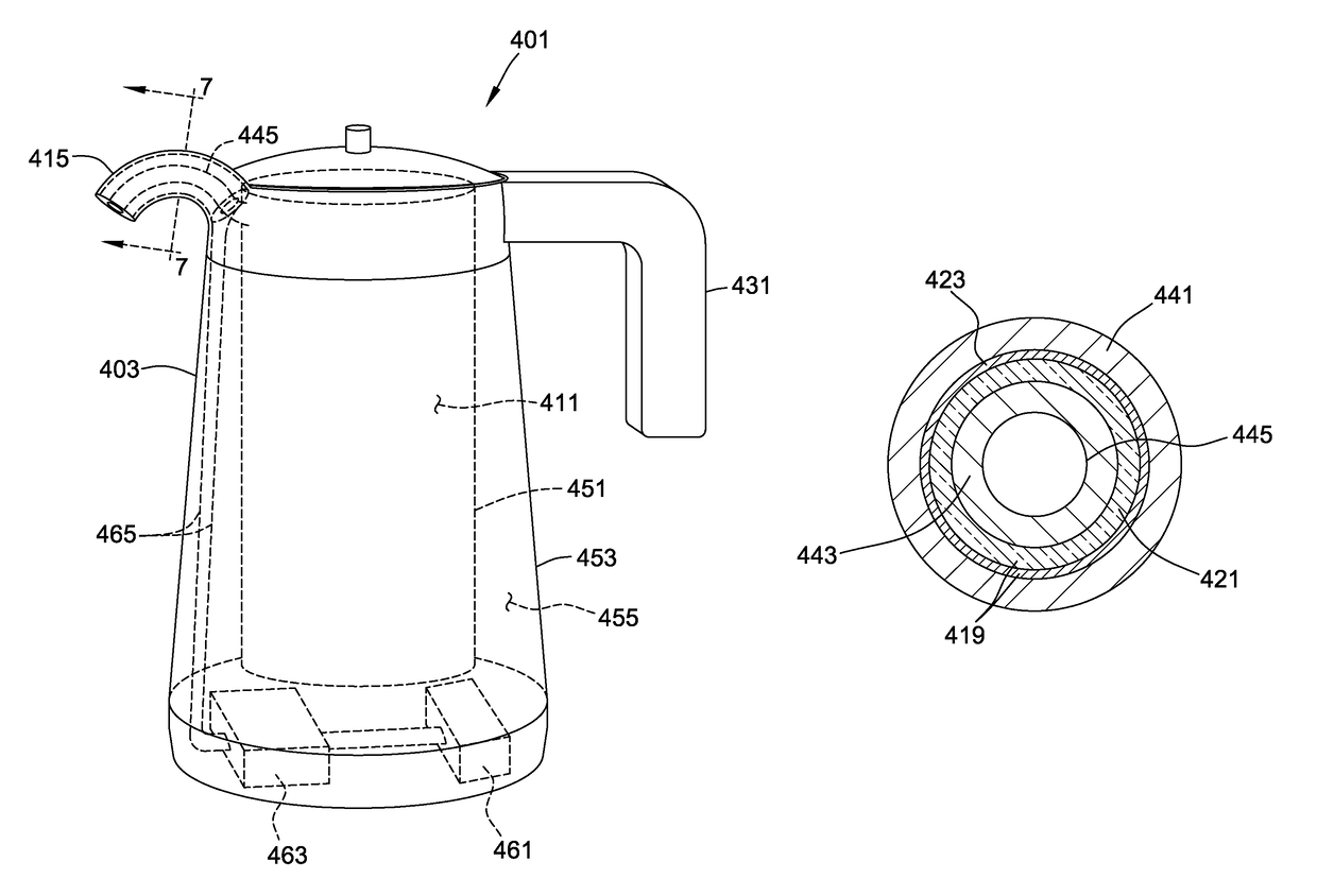
[0036]FIG. 5 illustrates a third embodiment that is similar to the embodiment of FIG. 3 in all respects, but with the base 231 of the system 201 of FIG. 3 omitted. Instead, the side wall 309 of the container 303 of this embodiment is configured to include a thin film heating element 319. In particular, the side wall 309 is multi-layered including an outer barrier layer 341, an electrically conductive thin film layer 323, a substrate layer 321 and an inner barrier layer 343 defining the interior reservoir 311 of the container 303.

[0037]The inner barrier layer 343 is suitably electrically non-conductive and thermally conductive or thermally transparent so that heat generated by the heating element 319 is readily conducted to and / or radiated through the inner barrier layer into the reservoir 311. It is understood that the inner barrier layer 343 may be multiple layers, as in the illustrated embodiment, or it may be a single layer of material within the scope of this invention.

[0038]The...


PUM


Abstract

In a portable container system for heating a beverage generally, the system includes a container for containing a beverage to be heated. The container generally has a bottom and a side wall together defining an internal reservoir containing the beverage to be heated. A base of the system is operable to heat the container at the bottom thereof. The base is constructed of multiple layers generally including at least a top barrier layer, an electrically non-conductive bottom barrier layer and a thin film heating element intermediate the top barrier layer and the bottom barrier layer.

Description

CROSS-REFERENCE TO RELATED APPLICATIONS[0001]This application claims the benefit of U.S. Provisional Application No. 61 / 980,468 filed on Apr. 16, 2014, and to Provisional Application No. 62 / 014,279 filed on Jun. 19, 2014, both of which are incorporated by reference.BACKGROUND[0002]The present invention relates generally to portable container systems for heating beverages such as water, coffee, tea and like, and more particularly to such container systems that employ a thin film heating element.[0003]The present disclosure employs a thin film heating element as part of a portable container system used to heat a beverage. The term portable refers to the ability of the container, during or after heating of its contents, to be carried to a remote location for dispensing such as pouring into a cup. Such portable container systems typically include a container, by itself or in combination with a heating plate on which the container may seat during a heating operation. Suitable containers ...

Claims


Application Information

Patent Timeline
Patent Type & Authority Patents(United States)
IPC IPC(8): H05B3/68A47J31/46A47J36/14A47J27/21H05B3/48A47J31/44
CPCH05B3/68A47J27/21191A47J27/2105A47J27/21008A47J27/21041A47J31/441A47J31/46A47J31/465A47J36/14H05B3/48H05B2203/021H05B2203/013
Inventor EVERETT, JR., DAVID WILLIAMNELSON, CHARLESROSATI, DANIELEMARSCHKE, KARL WARNER
Owner RAYOVAC CORP
Why Eureka
Try Eureka