
Magnetic and/or electrostatic resonator

a resonator and electrostatic technology, applied in the field of timepiece resonators, can solve the problems of affecting the quality factor and efficiency, and the difficulty of reconciling the very different frequencies of the components of the resonator, and achieve the effect of greater efficiency

Active Publication Date: 2017-05-16
NIVAROX FAR
View PDF7 Cites 0 Cited by
  • Summary
  • Abstract
  • Description
  • Claims
  • Application Information

AI Technical Summary

Benefits of technology

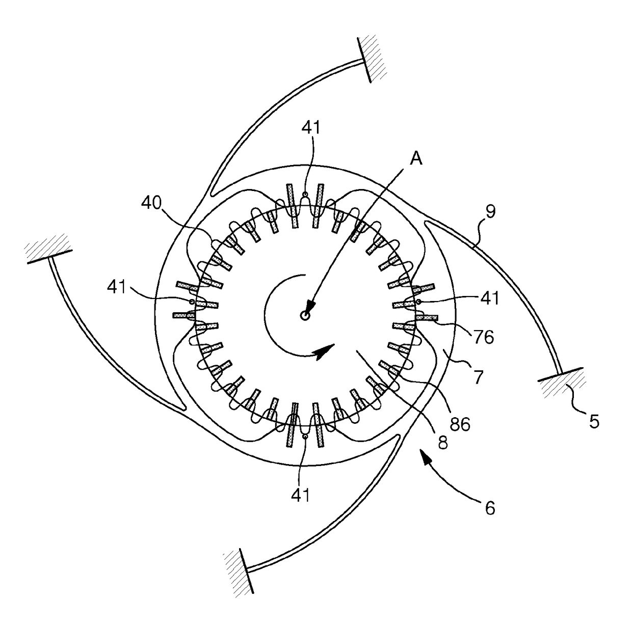
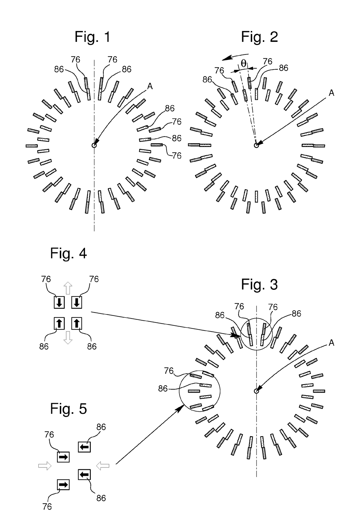
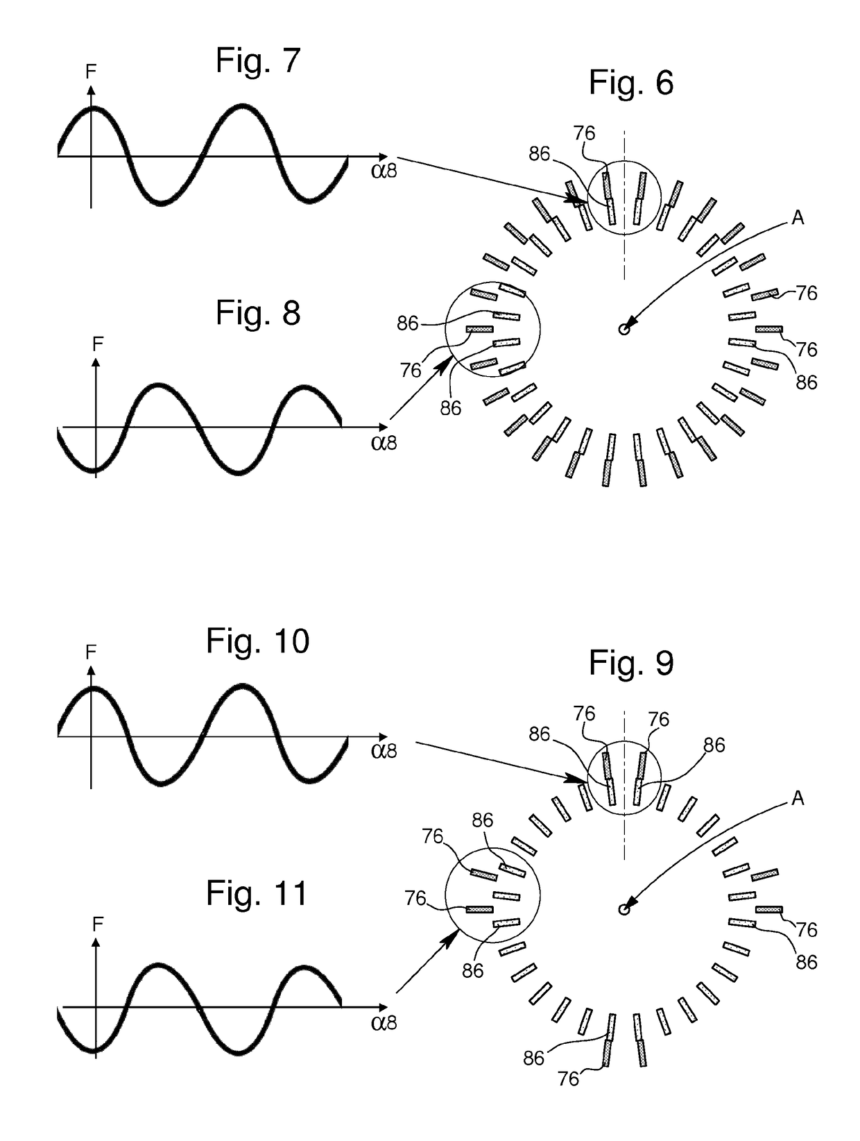
The invention proposes to create mechanisms that are more efficient than conventional resonators. This is achieved by using an annular magnetic or electrostatic resonator where the mobile component is periodically excited by the motion of the drive member. The mobile component is flexible and deformable at least in a plane in which it oscillates, and is charged with a first pitch angle by the drive member. The drive member is charged with a second pitch angle different from the first. These two areas attract or repel each other, creating a speed reducing or increasing mechanism. The speed of the drive member determines the speed of propagation of a wave of deformation in the mobile component all round it. The invention also includes a timepiece movement with an energy storage means and a mechanism actuated by a gear train, which controls display means of the movement. The invention also includes a timepiece with such a movement, such as a watch.

Problems solved by technology

The numerous contacts in a regulating member impair the quality factor and efficiency.
It is, moreover, difficult to reconcile the very different frequencies of the components of a resonator.

Method used


Image

  • Magnetic and/or electrostatic resonator
  • Magnetic and/or electrostatic resonator
  • Magnetic and/or electrostatic resonator

Examples


Embodiment Construction

[0021]Hereafter, a “ring” means a volume similar to an open torus, extending, closed on itself, about an axis. This ‘ring’ is substantially a surface of revolution about the axis, but not necessarily exactly of revolution about the axis.

[0022]The invention may be implemented with the involvement of magnetic and / or electrostatic fields. It is more particularly illustrated in a magnetic variant.

[0023]The invention concerns a timepiece resonator 6, comprising a mobile component 7 arranged to be capable of oscillation about an axis A, and a drive member 8 subjected to a torque inside a timepiece movement 10.

[0024]According to the invention, this resonator is a substantially annular magnetic or electrostatic resonator 6, whose mobile component 7 is periodically excited under the action induced by the motion of drive member 8; said drive member 8 is arranged to exert a contactless effort on mobile component 7.

[0025]Mobile component set 7 is flexible and deformable at least in a plane perp...


PUM


Abstract

A timepiece resonator including a mobile component ring-shaped about an axis and capable of oscillation about an axis, and a drive member subjected to a torque inside a timepiece movement. The resonator is an annular magnetic or electrostatic resonator whose mobile component is periodically excited under action induced by motion of the drive member. The drive member can exert a contactless effort on the mobile component. The mobile component includes a first quantity of first pole pieces magnetically or electrically charged at a first pitch angle, and the drive member includes a second quantity of second pole pieces magnetically or electrically charged at a second pitch angle different from the first pitch angle, arranged to cooperate in attraction or in repulsion with the first pole pieces, such that the mobile component and the drive member together form a speed reducing or increasing mechanism.

Description

CROSS-REFERENCE TO RELATED APPLICATIONS[0001]This is a National phase application in the United States of International patent application PCT / EP2014 / 076991 filed Dec. 9, 2014 which claims priority on Swiss Patent Application No. 02140 / 13 of Dec. 23, 2013 - European Patent Application No. 13199427.9 of Dec. 23, 2013 - Swiss Patent Application No. 02141 / 13 of Dec 23, 2013 - European Patent Application No. 13199428.7 of Dec. 23, 2013 - Swiss Patent Application No. 01057 / 14 of Jul. 11, 2014 - European Patent Application No. 14176816.8 of Jul. 11, 2014 - Swiss Patent Application No. 01365 / 14 of Sep. 09, 2014 - European Patent Application No. 14184158.5 of Sep. 09, 2014 - Swiss Patent Application No. 01416 / 14 of Sep. 19, 2014 - European Patent Application No. 14185638.5 of Sep. 19, 2014 and European Patent Application No. 14186652.5 of Sep. 26, 2014. The entire disclosures of the above patent applications are hereby incorporated herein by reference.FIELD OF THE INVENTION[0002]The inventi...

Claims


Application Information

Patent Timeline
Patent Type & Authority Patents(United States)
IPC IPC(8): G04C5/00G04B15/14
CPCG04C5/005G04B15/14G04B17/32
Inventor STRANCZL, MARCDI DOMENICO, GIANNIWINKLER, PASCAL
Owner NIVAROX FAR
Learn More