Cage having an automatic door

a cage and automatic technology, applied in the field of mechanical equipment, can solve the problems of adding a level of complexity to the operation, and achieve the effect of simple and quick

Active Publication Date: 2017-05-30
ZHU HONGWEN
View PDF13 Cites 2 Cited by
  • Summary
  • Abstract
  • Description
  • Claims
  • Application Information

AI Technical Summary

Benefits of technology

[0014]Comparing the cage disclosed by the present invention with the prior arts, the advantages are positive and obvious. The present invention utilizes a lock structure formed between the bending portion at the upper end of the connecting rod and the hook on the door panel, utilize a spring to sustain the connecting rod still, utilize the lower end of the connecting rod and pedal to form a trigger structure, which all have overcome the failure caused by rusty or tightly fixed trigger mechanism. In the meantime, placing the door panel in its ready position is simple and quick, including lifting up the door panel by one hand, the door panel will lock in position quickly at an open state, no other minor adjustment is needed.

Problems solved by technology

The cage has solved the problems in the prior arts that the valve type of door can cause failure due to the trigger mechanism and locking the door in a ready position manually adding a level of complexity in its operation.

Method used


Image

  • Cage having an automatic door
  • Cage having an automatic door
  • Cage having an automatic door

Examples


example 1

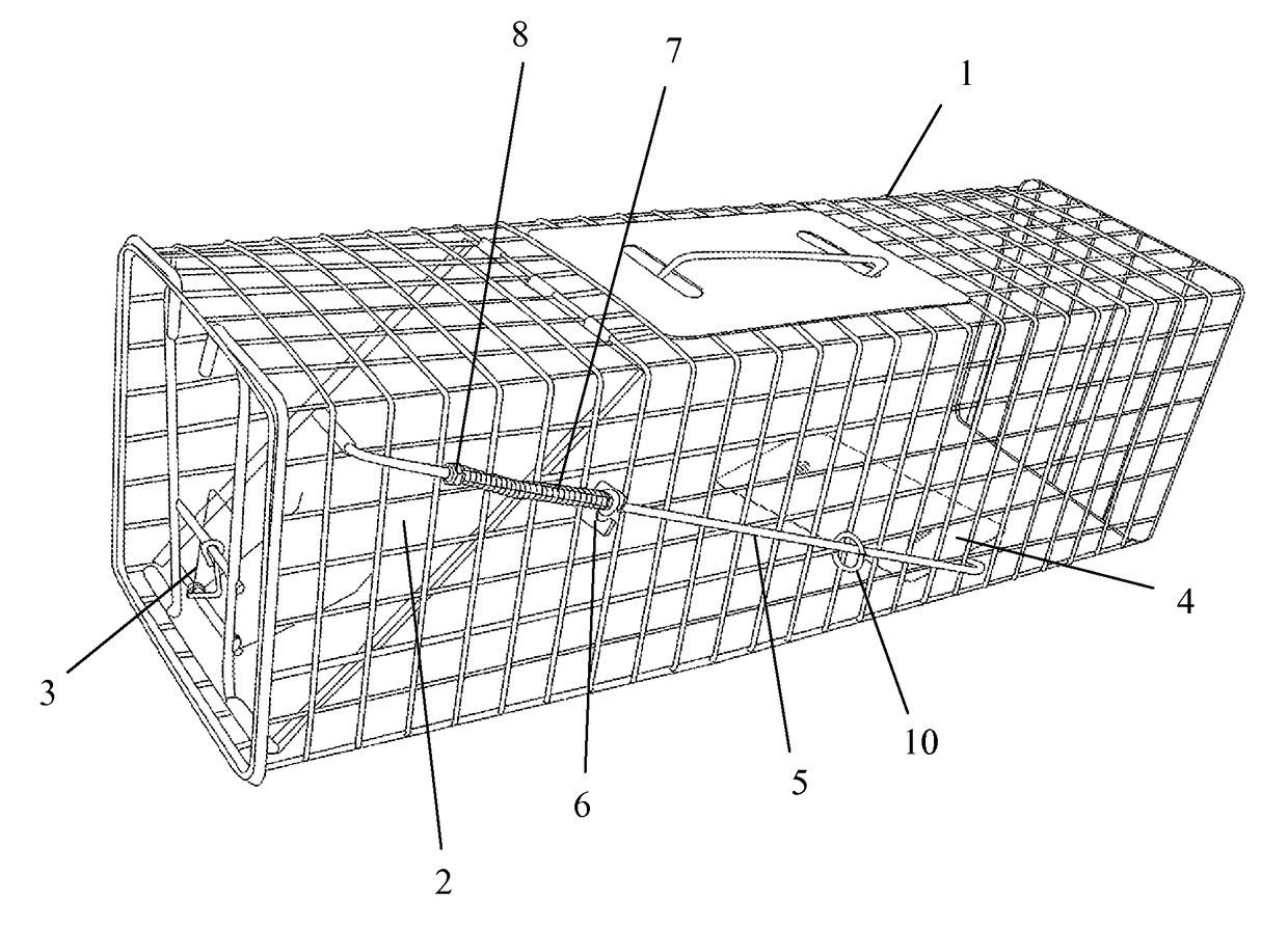
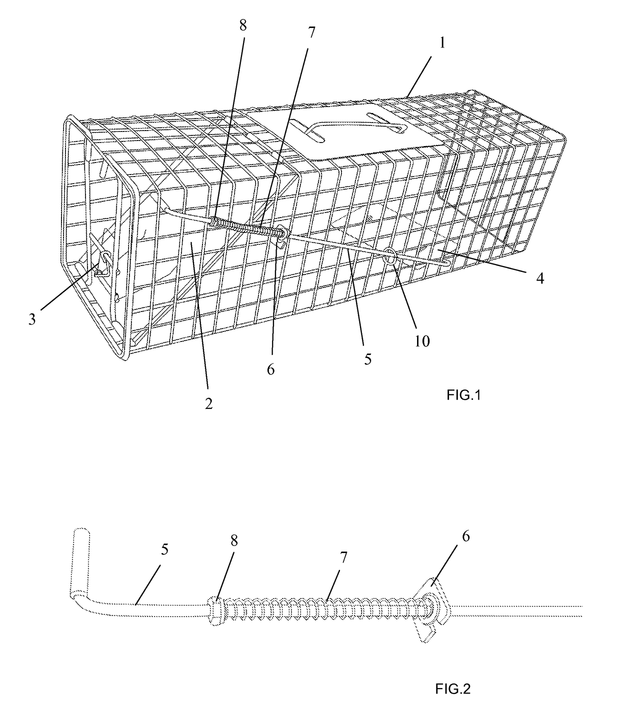
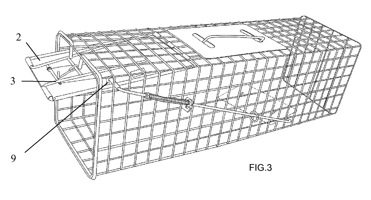
[0018]As shown in FIG. 1, the cage having an automatic door disclosed by the present invention, comprises a cuboid shaped cage 1. A front side of said cage 1 is provided with an opening. A door panel 2 is disposed at the front opening and inside the cage 1. The door panel 2 has a length greater than a height of the cage 1. A top edge of the door panel 2 is placed inside the cage 1, connected to a top surface of the cage 1 through a hinge structure. A spring device 3 is arranged between a lower edge of the door panel 2 and the cage 1, and the spring device 3 makes the lower edge of the door panel 2 lean towards a bottom surface of the cage 1. A pedal 4 is disposed on the bottom surface inside the cage 1. A front edge of the pedal 4 is connected to the bottom surface of the cage 1 through another hinge structure. Wherein, the pedal 4 is connected with a connecting rod 5. A pair of rotation joints is placed between a lower end of the connecting rod 5 and the pedal 4. An upper end of th...


PUM


Abstract

A cage having an automatic door is described. A front side of the cage is provided with a door panel. A top edge of the door panel is hingely attached to the cage. A bottom edge of the door panel is attached to the cage through a spring. A pedal is provided on a bottom surface of the cage. A front side of the pedal is hingely attached to the cage. The pedal is connected with a connecting rod. An upper end of the connecting rod extends upward and forward along a sidewall of the cage and is bent towards an exterior of the door panel. A spring supporting seat is fixed on the sidewall of the cage. Said spring supporting seat is connected with a spring. The connecting rod is fixedly provided with a spring contact point. Spring can move the connecting rod up toward the top of the cage and forward toward the front of the cage to lift up the pedal. A hook is fixedly provided on an outer surface of the door panel. An opening of the hook faces the top of the cage. When the door panel is in its fully open position, a bending portion of the upper end of the connecting rod locks into the hook. When the pedal is pressed down, the connecting rod is pulled downwardly and detached from the hook. The door panel moves down automatically to close the cage. In case of trigger mechanism failure, the door panel can be lifted by one hand, and quickly and automatically locks in position to restart, no other manual adjustment is needed.

Description

CROSS REFERENCE TO RELATED APPLICATIONS[0001]This application claims the benefit of a Chinese application 201520010190.5, filed Jan. 8, 2015. The subject matter as set forth in the Chinese application is incorporated herein by reference in its entirety.TECHNICAL FIELD[0002]The invention relates to a mechanical apparatus, in particular relates to a tool to capture an animal, particularly a trap having an automatic door.BACKGROUND OF THE INVENTION[0003]For manufacturing, everyday living and research purpose, sometimes it is needed to capture a small live animal. In the prior art, a valve type automatic door traps are used to capture the fox, mink, squirrels and other small animals. This kind of valve type automatic door trap comprises a cuboid shaped metal wire braided cage, having a front opening, the front opening of the cage is provided with a door panel, the upper edge of the door panel is connected with the cage by a hinge structure, a spring device is arranged between the lower ...

Claims


Application Information

Patent Timeline
Patent Type & Authority Patents(United States)
IPC IPC(8): A01M23/00A01M23/18A01M23/08A01M23/20
CPCA01M23/20A01M23/08A01M23/18
Inventor ZHU, HONGWEN
Owner ZHU HONGWEN
Why Eureka
Try Eureka