Data processing apparatus and print data generating method determining a dot arrangement pattern using a code table

a data processing apparatus and a code table technology, applied in the direction of matrix printers, visual presentations, instruments, etc., can solve the problem of another texture problem in the print imag

Active Publication Date: 2017-06-06
CANON KK
View PDF10 Cites 0 Cited by
  • Summary
  • Abstract
  • Description
  • Claims
  • Application Information

AI Technical Summary

Benefits of technology

[0008]An object of the present invention is to provide a data processing apparatus and a print data generating method that enable the frequencies of generation of offset values to be made uniform even when an offset value is indivisible by the size of a matrix or a code table for dot arrangement patterns.
[0011]The above-described configuration enables the frequencies of generation of the offset values to be made uniform even when an offset value is indivisible by the size of a matrix or a code table for dot arrangement patterns.

Problems solved by technology

As a result, the frequencies at which the offset pixel numbers are selected are biased, possibly resulting in another texture problem with the print image.

Method used


Image

  • Data processing apparatus and print data generating method determining a dot arrangement pattern using a code table
  • Data processing apparatus and print data generating method determining a dot arrangement pattern using a code table
  • Data processing apparatus and print data generating method determining a dot arrangement pattern using a code table

Examples


first embodiment

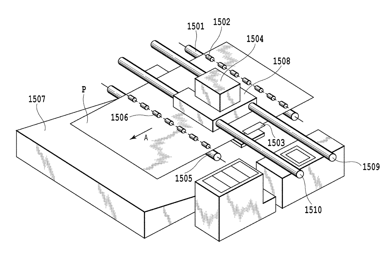
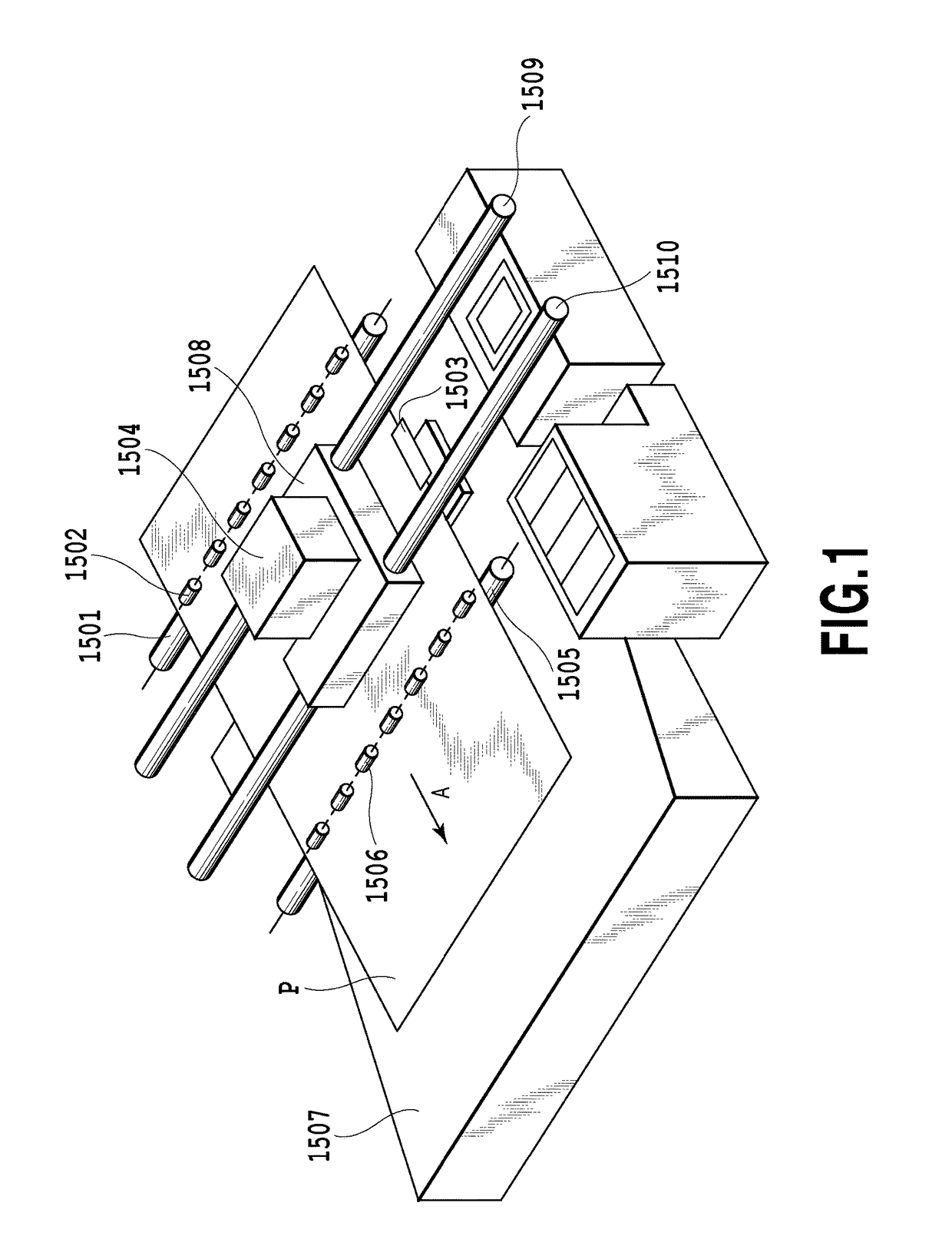
[0028]FIG. 1 is a perspective view showing a general configuration of an inkjet printing apparatus according to an embodiment of the present invention. A print medium P such as a sheet is sandwiched between a conveying roller 1501 and a pinch roller 1502 that follows the conveying roller 1501 while elastically biasing the print medium toward the conveying roller 1501. The print medium is conveyed in the direction of arrow A in FIG. 1 in conjunction with rotation of the conveying roller 1501 while being guided and supported by a platen 1503. The platen 1503 is provided in a print area opposite to a surface of a print head in which an ejection port is formed (ejection surface); the print head is mounted in a carrier 1508 to eject ink. The platen 1503 supports a back surface of the print medium P to keep a constant distance or a predetermined distance between a surface of the print medium P and the ejection surface. After being conveyed on the platen 1503 and printed, the print medium ...

second embodiment

[0060]FIG. 12 is a diagram illustrating conversion of offset values in the X direction in the offset value generating part 304 according to a second embodiment of the present invention. FIG. 12 is similar to FIG. 7 according to the first embodiment. In conversion of offset values, the offset value generating part 304 (FIG. 5) may use the number of generations for each offset value that exceeds the code table size. In FIG. 12, a data counter 603 for an offset value of 6 has an initial value of 0, and a data counter 604 for an offset value of 7 has an initial value of 1. For each offset value of 6 derived from the random number generating part 303, the data counter 603 converts the offset value of 6 into the current count value and increments the count value. The count value returns to 0 when the data counter 603 counts up to a value (5) corresponding to the table size. This also applies to a data counter 604 for an offset value of 7. Consequently, also in the present embodiment, the ...

third embodiment

[0062]FIG. 13 is a diagram illustrating conversion of offset values in the X direction by the offset value generating part 304 according to a third embodiment of the present invention. FIG. 13 is similar to FIG. 7 according to the first embodiment. The offset value generating part 304 (FIG. 5) includes a common counter 605 that counts up when the offset value acquired from the random number generating part 303 is 6 or 7. An initial value can be set for the common counter 605, and in the illustrated example, an initial value of 0 is set. For each offset value of 6 derived from the random number generating part 303, the common counter 605 converts the offset value of 6 into the current count value and increments the count value. The count value returns to 0 when the common counter 605 counts up to a value (5) corresponding to the table size. A similar configuration is used to convert the offset value for the Y direction. Thus, offset values of 0 to 5 are generated for a code table wit...


PUM


Abstract

A data processing apparatus includes a holding unit holding a code table, in which each of the codes in the table determines the dot arrangement pattern, a determining unit determining a predetermined number of first offset values which is power of 2, the first offset values denoting a number of pixels by which an arrangement of the codes is shifted in the code table, a table generating unit, in a case where a size of the code table is not power of 2 and the determining unit determines the first offset value wherein a quotient and a remainder when the predetermined number is divided by the size is 1 or more, determining a second offset value wherein the quotient is zero, as substitute for the determined first offset value, and to generate the code table to which an offset is made with the second offset value.

Description

BACKGROUND OF THE INVENTION[0001]Field of the Invention[0002]The present invention relates to a data processing apparatus and a print data generating method, and in particular, to a technique for making an offset in an arrangement of a plurality of dot arrangement patterns used to binarize image data.[0003]Description of the Related Art[0004]In a dot arrange pattern, “printing (dots present)” or “non-printing (no dots)” is determined in each pixel of a unit of one pixel×two pixels which has a double resolution of 1,200 dpi in a longitudinal direction, according to a gradation value of image data. In binary data generation, gradation values indicated by image data of 600 dpi can be converted into binary data (dots present / no dots) within the range of one pixel×two pixels, using dot arrangement patterns corresponding to the gradation value indicated by the image data. This binarization technique enables data processing, transfer, and the like to be executed in a low-resolution data fo...

Claims


Application Information

Patent Timeline
Patent Type & Authority Patents(United States)
IPC IPC(8): G06K15/02G06K15/10H04N1/40H04N1/405
CPCG06K15/1843G06K15/107G06K15/1802G06K15/1848H04N1/40H04N1/405H04N1/52
Inventor UEKI, HIDEYUKI
Owner CANON KK
Why Eureka
Try Eureka