Discharge lamp driver, light source, projector, and method of driving discharge lamp

a discharge lamp and driver technology, applied in the direction of picture reproducers, picture reproducers using projection devices, instruments, etc., can solve the problems of arc tubes, evaporation electrode material may attach to the inner wall of arc tubes and blacken, and devitrification is likely to occur, so as to suppress devitrification, electrode wear and blackening may be effectively suppressed, and electrode wear and blackening may be suppressed

Inactive Publication Date: 2017-08-08
SEIKO EPSON CORP
View PDF7 Cites 0 Cited by
  • Summary
  • Abstract
  • Description
  • Claims
  • Application Information

AI Technical Summary

Benefits of technology

[0011]An advantage of some aspects of the invention is to provide a discharge lamp driver that suppresses both blackening and devitrification and electrode wear of a discharge lamp and improves the life of the discharge lamp, and a light source using the discharge lamp driver, a projector using the light source. Another advantage of some aspects of the invention is to provide a method of driving the discharge lamp that suppresses both blackening and devitrification and electrode wear of the discharge lamp and improves the life of the discharge lamp.

Problems solved by technology

However, for example, in the method disclosed in Patent Document 1, the evaporated electrode material may attach to the inner wall of the arc tube and blacken.
In this case, the electrode material attaching to the inner wall of the arc tube raise the temperature of the inner wall of the arc tube and devitrification is likely to occur.
Further, for example, in the method disclosed in Patent Document 2, the high frequency is used as the drive current, the temperature variations of the electrodes decrease and the electrodes are likely to be worn in a short period.
Accordingly, for example, in application to a projector, in order to improve use efficiency of light, it is preferable to maintain the smaller distance between electrodes and reduce the magnitude of light emission, however, for suppression of electrode wear, suppression of blackening and devitrification is difficult and, for suppression of blackening and devitrification, suppression of electrode wear is difficult.
Therefore, it has been difficult to achieve a good balance between the suppression of blackening and devitrification and the suppression of electrode wear and extend the life of the discharge lamp.

Method used


Image

  • Discharge lamp driver, light source, projector, and method of driving discharge lamp
  • Discharge lamp driver, light source, projector, and method of driving discharge lamp
  • Discharge lamp driver, light source, projector, and method of driving discharge lamp

Examples


first embodiment

[0108]As below, the drive current waveform will be explained.

[0109]FIG. 8 is a timing chart showing an example of drive current waveform DW1 of the embodiment. The control unit 40 controls the discharge lamp drive unit 230 according to the drive current waveform DW1. The horizontal axis indicates time T and the vertical axis indicates current I.

[0110]As shown in FIG. 8, in the drive current waveform DW1, a waveform pattern in a control cycle C1 is continuously formed.

[0111]The control cycle C1 has a first mixed frequency drive period PM1, low-frequency drive periods PL, and a second mixed frequency drive period PM2. The low-frequency drive periods PL are respectively provided immediately after the first mixed frequency drive period PM1 and immediately after the second mixed frequency drive period PM2. The control cycle C1 is repeated, and thereby, the first mixed frequency drive period PM1 and the second mixed frequency drive period PM2 are alternately repeated.

[0112]The first mixed...

second embodiment

[0141]As below, the drive current waveform will be explained.

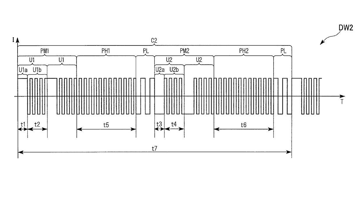
[0142]FIG. 9 is a timing chart showing an example of drive current waveform DW2 of the embodiment.

[0143]As shown in FIG. 9, in the drive current waveform DW2, a waveform pattern in a control cycle C2 is continuously formed.

[0144]The control cycle C2 has a first mixed frequency drive period PM1, a first high-frequency drive period PH1, low-frequency drive periods PL, a second mixed frequency drive period PM2, and a second high-frequency drive period PH2. The low-frequency drive periods PL are respectively provided immediately after the first high-frequency drive period PH1 and immediately after the second high-frequency drive period PH2.

[0145]The first high-frequency drive period PH1 and the second high-frequency drive period PH2 are periods in which a high-frequency alternating current higher than 1000 Hz and equal to or smaller than 10 GHz flows between electrodes.

[0146]The total length of the length t5 of the first high-...


PUM


Abstract

A discharge lamp driver includes a discharge lamp drive unit that supplies a drive current to the discharge lamp, and a control unit that controls the discharge lamp drive unit according to a drive current waveform, wherein the drive current waveform has a mixed frequency drive period including a unit drive period containing a first drive period in which a first drive current is supplied to the discharge lamp and a second drive period provided immediately after the first drive period, in which a second drive current is supplied to the discharge lamp, the first drive current is a half-period alternating current having a frequency higher than 10 Hz and not higher than 300 Hz, the second drive current is an alternating current having a frequency higher than 1000 Hz, and a length of the second drive period is equal to or longer than a length of the first drive period.

Description

BACKGROUND[0001]1. Technical Field[0002]The present invention relates to a discharge lamp driver, a light source, a projector, and a method of driving a discharge lamp.[0003]2. Related Art[0004]Discharge lamps including high-pressure mercury lamps used for projectors or the like emit light by arc discharge within gases in plasma state. The arc discharge produces various reactions within the discharge lamp and causes illuminance reduction of the discharge lamp. There is a task of suppressing the illuminance reduction of the discharge lamp and extending the life of the discharge lamp.[0005]Generally, as causes of the illuminance reduction of the discharge lamp, three main causes of blackening that electrode materials evaporated by arc discharge attach to the inner wall of the arc tube of the discharge lamp, devitrification that the inner wall of the arc tube is crystallized to be opaque due to its higher temperature and transmittance is lower, and electrode wear due to arc discharge a...

Claims


Application Information

Patent Timeline
Patent Type & Authority Patents(United States)
IPC IPC(8): H05B41/34H04N9/31H05B41/288G03B21/20
CPCH04N9/3155H05B41/2886G03B21/2026
Inventor SUZUKI, JUNICHISATO, SHUN
Owner SEIKO EPSON CORP
Why Eureka
Try Eureka