Eureka AIR delivers breakthrough ideas for toughest innovation challenges, trusted by R&D personnel around the world.

Touch operation input device, touch operation input method and program

a technology of touch operation and input device, applied in the direction of instruments, computing, electric digital data processing, etc., can solve the problem of remaining strokes

Active Publication Date: 2017-09-12
SHARP KK
View PDF12 Cites 2 Cited by
  • Summary
  • Abstract
  • Description
  • Claims
  • Application Information

AI Technical Summary

Benefits of technology

[0014]According to the present invention, even in the drawing mode, since no drawn image will be displayed at the touched area when a touch is performed for a menu process, it is possible to avoid the menu being hard to read due to residue of the drawn image and it is no longer necessary for the user to erase the drawn image.

Problems solved by technology

Further, even when the menu is cancelled by a long press, the stroke also remains.
As a result, the user has to erase the stroke trace (spot) every time it is drawn, causing inconvenience.

Method used


Image

  • Touch operation input device, touch operation input method and program
  • Touch operation input device, touch operation input method and program
  • Touch operation input device, touch operation input method and program

Examples


first embodiment

The First Embodiment

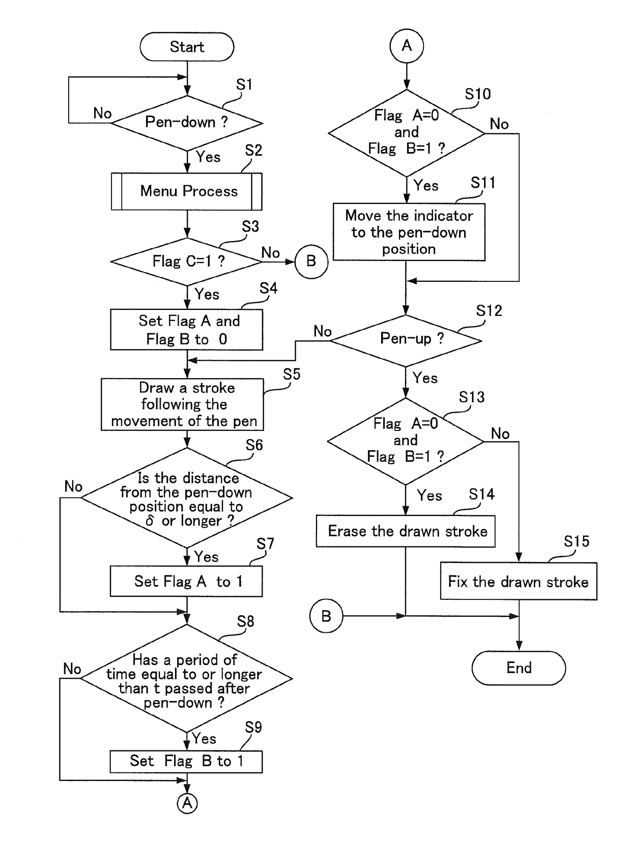
[0039]FIG. 3 is a flow chart showing a process of drawing mode in the first embodiment of the touch operation input device according to the present invention. FIG. 4 is a flow chart showing the menu process.

[0040]In drawing mode, a line image is formed following a stroke of a touch operation. However, when a menu display operation is performed, a line is also drawn along the stroke. This drawing is actually the part that is unwanted to be drawn, so that an erasing process of this part is performed.

[0041]The first embodiment shows a configuration that is applied to a case where a single touch pen 15 (FIG. 1) is used.

[0042]In drawing mode, operation processor 21 (FIG. 2) checks whether touch operation detector 12 (FIGS. 1 and 2) has detected a landing of touch pen 15 (Step S1). Then, touch operation input device 10 (FIGS. 1 and 2) performs a menu process (Step S2).

[0043]As shown in FIG. 4, operation processor 21 sets a flag C to 0 (Step S21). Next, menu processor 2...

second embodiment

The Second Embodiment

[0063]FIGS. 11 and 12 are illustrative views showing a menu control process in the second embodiment of a touch operation input device according to the present invention.

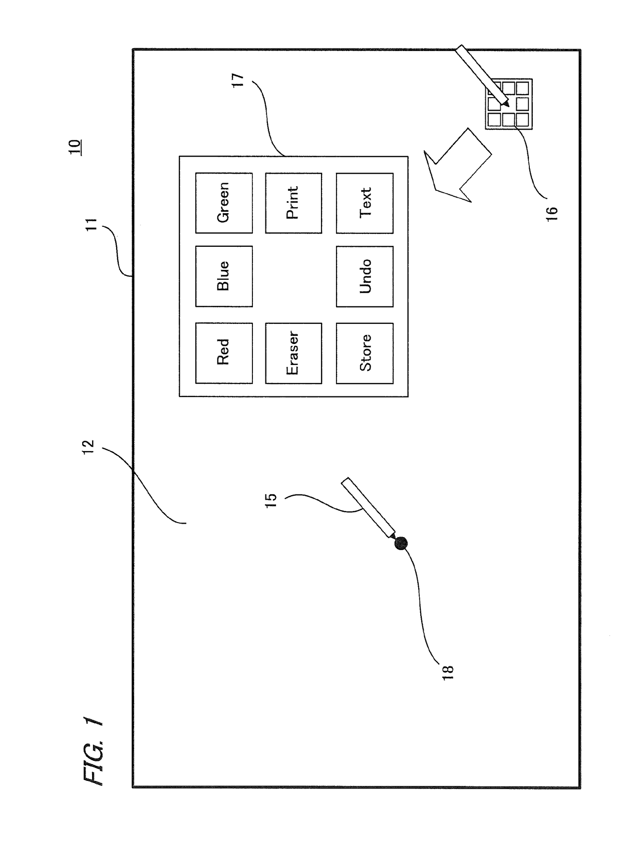
[0064]This configuration includes a plurality of pens and a plurality of users, each having the pen, can perform different operations at the same time. In this embodiment, there are three pens for three users, and indicator menu 16 exists for each.

[0065]Though not illustrated, a square menu exists corresponding to each indicator menu 16. Each of the square menus can be displayed individually and erased separately. The menu items of each square menu may be the same as, or different from, those of the others.

[0066]The control as to menus is performed by each touch pen, following the flow charts shown in FIGS. 3 and 4.

[0067]For example, as shown in FIG. 11, when the screen is long pressed by each touch pen 15, each indicator menu 16 corresponding to each touch pen 15 moves to the pen-down position ...


PUM


Abstract

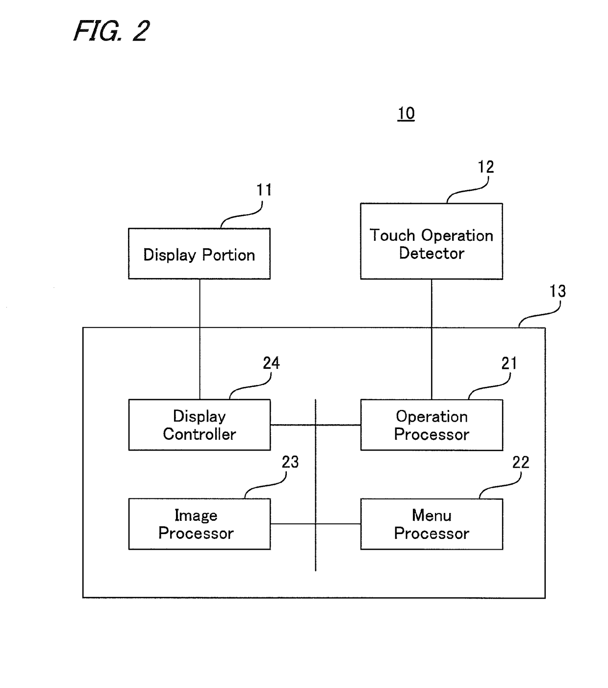
A touch operation input device that allows input by a touch operation to a display screen, has a touch operation detector for detecting a touch operation; an operation processor for performing a process by determining operated content based on a detection result of the touch operation detector; a menu processor for performing a menu displaying process and a process of a menu item, based on a determination result of the operation processor; an image processor for performing a process of generating a drawn image on a touched portion when in a drawing mode; and a display controller for performing control of display on a display screen. When the operation processor has determined the touch operation as an operation for a menu process, the image processor performs a process of erasing the drawn image drawn by the touch operation even in the drawing mode.

Description

[0001]This Nonprovisional application claims priority under 35 U.S.C. §119 (a) on Patent Application No. 2014-085306 filed in Japan on 17 Apr. 2014, the entire contents of which are hereby incorporated by reference.BACKGROUND OF THE INVENTION[0002](1) Field of the Invention[0003]The present invention relates to a touch operation input device, touch operation input method and program in which menu is displayed in drawing mode by performing a touching operation so as to select and input an operation item.[0004](2) Description of the Prior Art[0005]Recently, touch operation input devices such as tablet terminals, electronic blackboards and the like that allow the user to input by touching operation have appeared. In input operation in such the touch operation input device, an operation menu is displayed so that the user can operate the device intuitively. Examples of how the operation menu is displayed include a type in which the operation menu is constantly displayed at an edge of the...

Claims


Application Information

Patent Timeline
Patent Type & Authority Patents(United States)
IPC IPC(8): G06F3/048G06F3/0488G06F3/0482G06F3/041
CPCG06F3/04883G06F3/0416G06F3/0482
Inventor KOYAMA, NORIYUKIAKITOMO, KENJI
Owner SHARP KK
Why Eureka
Eureka Blog
Learn More