
Method and apparatus for improving RFID tag reading

a technology of rfid tags and readers, applied in repeater circuits, line-transmission details, instruments, etc., can solve problems such as difficulty in reading some rfid tags placed in front of rfid readers, and achieve the effect of improving the reading of rfid tags with rfid readers and being difficult to read

Active Publication Date: 2013-04-09
SYMBOL TECH LLC
View PDF32 Cites 2 Cited by
  • Summary
  • Abstract
  • Description
  • Claims
  • Application Information

AI Technical Summary

Benefits of technology

[0006]Implementations of the invention can include one or more of the following advantages. The reading of RFID tags with RFID readers can be improved even when some of these RFID tags can be difficult to read without using the newly invented apparatus. These and other advantages of the present invention will become apparent to those skilled in the art upon a reading of the following specification of the invention and a study of the several figures in the drawings.

Problems solved by technology

Consequently, it can be difficult to read some of the RFID tags placed in front of an RFID reader when these RFID tags are incorrectly aligned with RFID reader.

Method used


Image

  • Method and apparatus for improving RFID tag reading
  • Method and apparatus for improving RFID tag reading
  • Method and apparatus for improving RFID tag reading

Examples


Embodiment Construction

[0015]FIG. 3 shows a part of an RFID reader 20 in one specific kind of implementation. In FIG. 3, the RFID reader 20 includes an antenna 28 coupled to a transmitter 22 and a receiver 24. The RFID reader 20 also includes a circulator 23, a demodulator 26, and a frequency generator 21.

[0016]In operation, the transmitter 22 generates an RF interrogation signal. This RF interrogation signal is coupled to the antenna 28 through the circulator 23. The electromatic waves radiated from the antenna 28 are then received by the antenna in an RFID tag. In response to the interrogation from the RFID reader, the RF tag will reflect back some responding electromagnetic waves coded with the identification information of the RF tag. The responding electromatic waves are picked up by the antenna 28 as a responding RF signal. The responding RF signal enters the circulator 23 and is received by the receiver 24. The RF signal received by the receiver, after amplification, is demodulated with demodulator...


PUM


Abstract

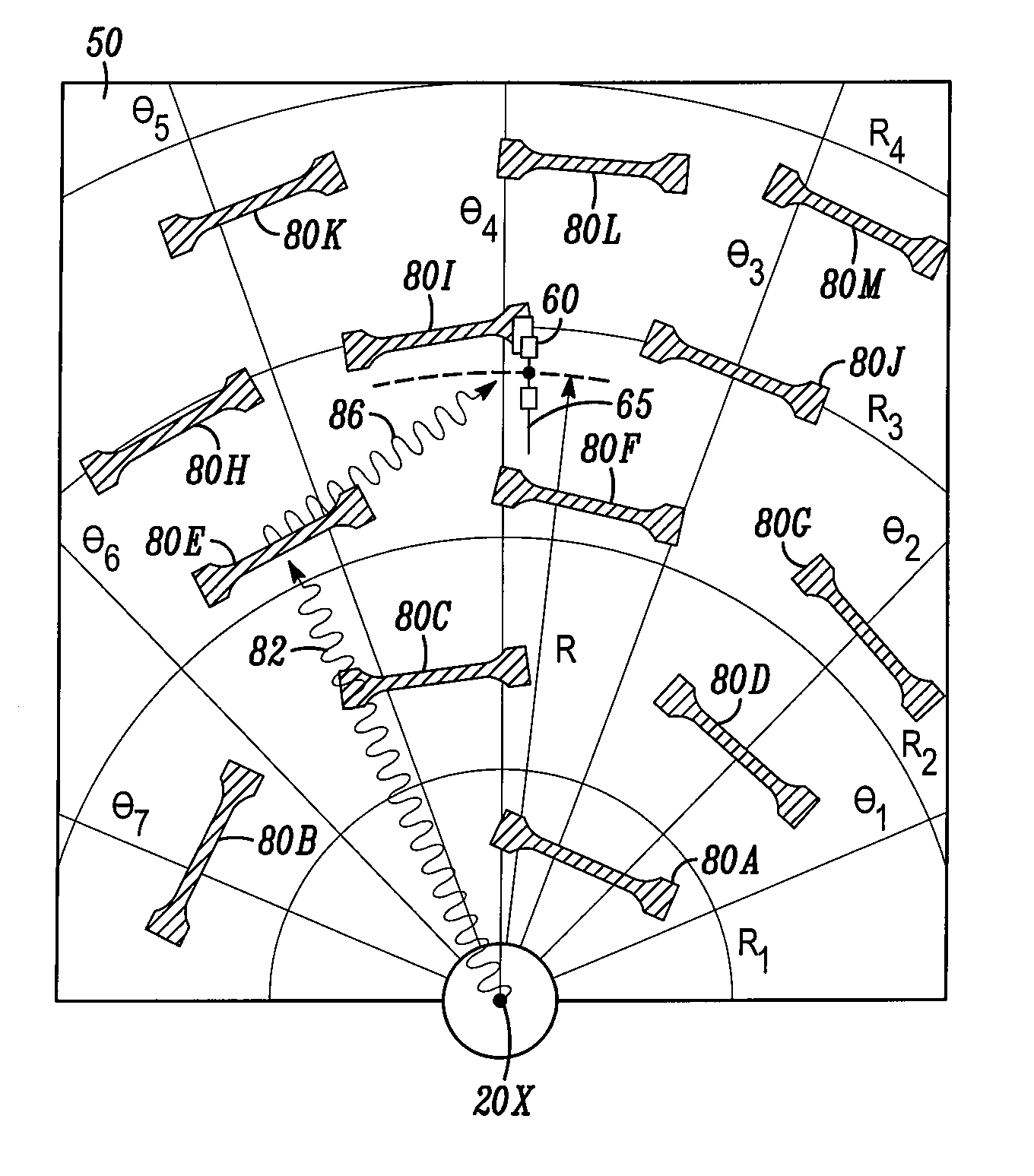
An apparatus and method for improving RFID tag reading. The apparatus includes a substrate element having a predetermined active area, and a plurality of resonant elements each having a resonant frequency, a quality factor, and a response band. The resonant elements are distributed within the predetermined active area of the substrate element for scattering interrogation electromagnetic waves radiated thereupon from the RFID reader. At least one resonant element has a null-direction thereof orientated in a direction that is substantially orthogonal to a line extending from a center of the resonant element to a center of an antenna of the RFID reader.

Description

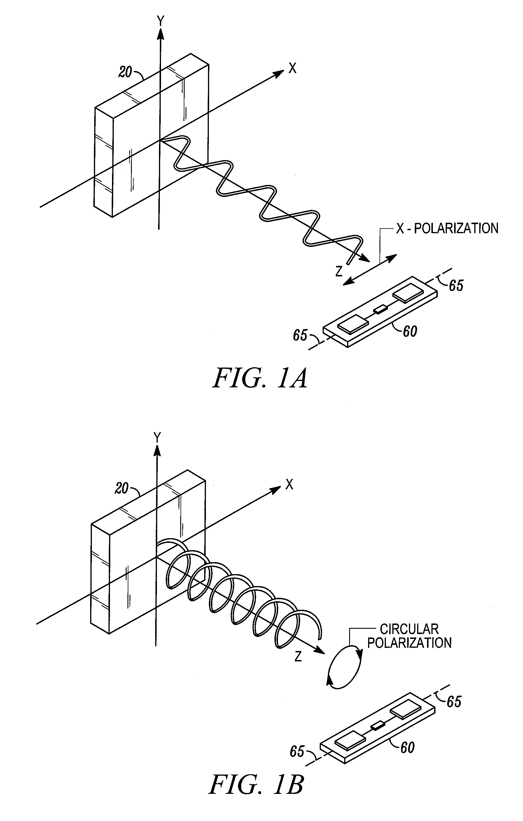
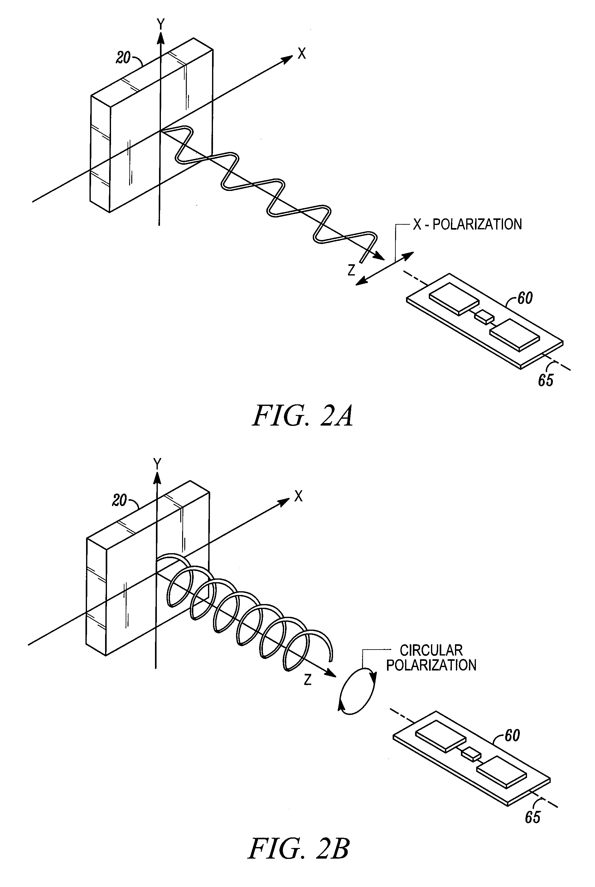
FIELD OF THE DISCLOSURE[0001]The present disclosure relates generally to RFID technology.BACKGROUND[0002]RFID technology generally involves interrogating an RFID tag with radio frequency (RF) waves and reading the responding RF waves with an RFID reader. An RFID tag typically includes a miniscule microchip coupled to an RF antenna. RFID tags can be attached to the object to be identified. An RFID reader typically includes an antenna coupled to a transmitter and a receiver.[0003]In many implementations, the antenna for the RFID tag has a null-direction in which no RF wave is radiated. For example, the radiation from a dipole antenna follows a toroidal radiation pattern with the central axis of the toroid representing the null-direction of the dipole antenna. When an RFID tag is located in the radiation range of the RFID reader, the electrical filed of the RF waves is generally transverse to the direction of propagation. The RFID tag tends to responds most to interrogating RF waves fr...

Claims


Application Information

Patent Timeline
Patent Type & Authority Patents(United States)
IPC IPC(8): H04Q5/22
CPCG06K7/0008G06K7/10178G06K7/109
Inventor AUSTIN, TIMOTHY B.
Owner SYMBOL TECH LLC
Learn More