CPR chest compression monitor and method of use

a chest compression and monitor technology, applied in the field of chest compression monitor and method of use, can solve the problems of cpr survival rate of 15%, current conventional cpr techniques introduced in 1960, limited success both inside and outside the hospital, etc., and achieve the effect of improving resuscitation techniques and improving the quality of li

Inactive Publication Date: 2002-05-09
THE JOHN HOPKINS UNIV SCHOOL OF MEDICINE
View PDF0 Cites 124 Cited by
  • Summary
  • Abstract
  • Description
  • Claims
  • Application Information

AI Technical Summary

Problems solved by technology

Current conventional techniques for CPR introduced in 1960 have had limited success both inside and outside of the hospital, with only about 15% survival rate.
Accordingly, the importance of improving resuscitation techniques cannot be overestimated.
If, however, more than a few minutes pass between the onset of ventricular fibrillation and the delivery of the first defibrillation shock, the heart may be so deprived of metabolic substrates that defibrillation is unsuccessful.
Unfortunately, however, studies indicate that CPR is performed correctly only part of the time--approximately 50% of the time according to a study conducted on 885 patients.
Even invasive interventions used in hospitals, such as open chest cardiac massage, have failed to improve survival rates, probably due to irreversible organ damage produced by prolonged schema during transportation.
Since there is no feedback, and since relatively small changes in the amount of compression can affect perfusion pressure, it is not surprising that CPR is often performed incorrectly.
However, these devices do not measure chest displacement.
This is problematic since with clinical CPR there is considerable variation in the compliance of different patients' chests, such th...

Method used


Image

  • CPR chest compression monitor and method of use
  • CPR chest compression monitor and method of use
  • CPR chest compression monitor and method of use

Examples


Embodiment Construction

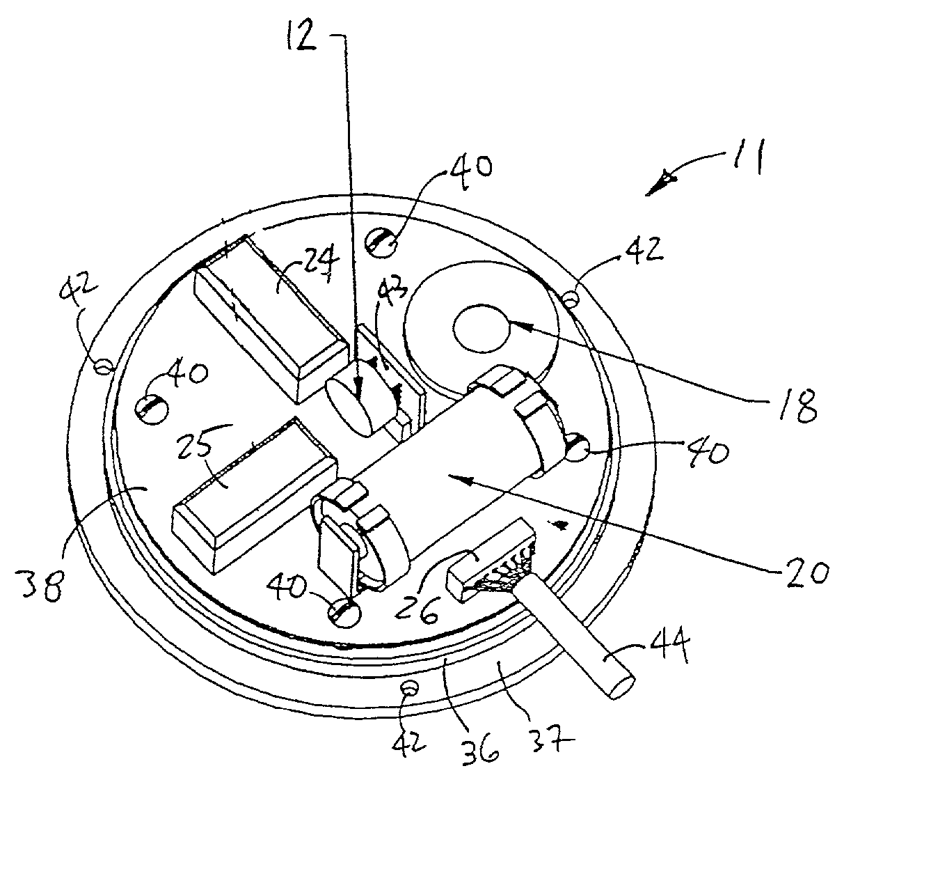
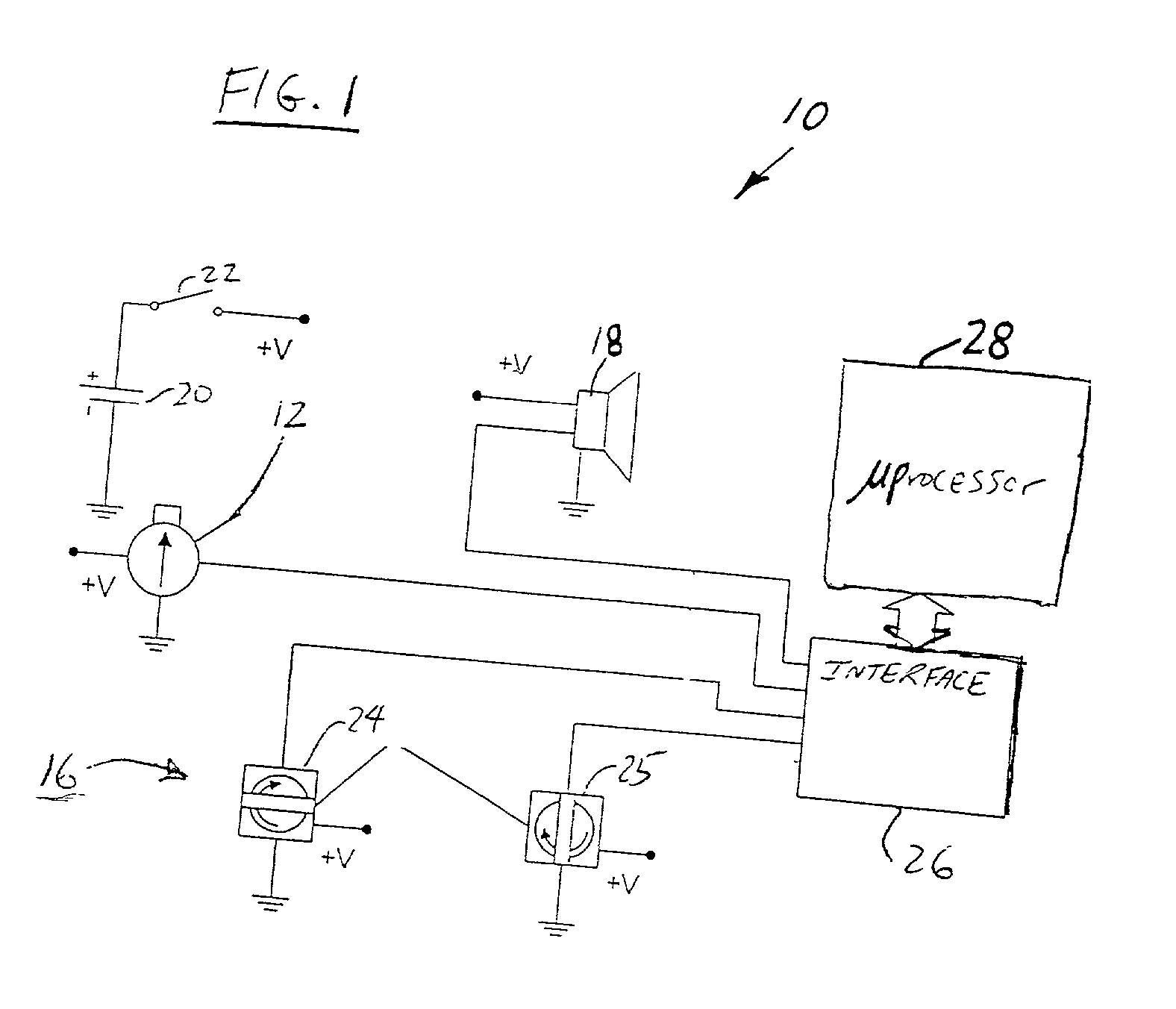
[0040] FIG. 1 is a schematic representation of one embodiment of a hand-held CPR chest compression monitor 10 for measuring the rate and depth of chest compressions during the administration of CPR. The illustrated monitor 10 is a specific implementation of a monitoring system for measuring and prompting chest compressions to facilitate the effective administration of cardiopulmonary resuscitation (CPR). The system comprises a displacement detector and a signaling mechanism. The displacement detector produces and outputs a displacement-indicative signal indicative of the displacement of a CPR recipient's chest toward the recipient's spine. The signaling mechanism provides chest compression indication signals directing a chest compression force applied to the chest and a frequency of compressions to bring and maintain the frequency and chest displacement parameters within desired ranges. The monitoring system may be further provided with a tilt compensator comprising a tilt sensor me...


PUM


Abstract

Chest compressions are measured and prompted to facilitate the effective administration of CPR. A displacement detector produces a displacement indicative signal indicative of the displacement of the CPR recipient's chest toward the recipient's spine. A signaling mechanism provides chest compression indication signals directing a chest compression force being applied to the chest and a frequency of such compressions. An automated controller and an automated constricting device may be provided for applying CPR to the recipient in an automated fashion. The automated controller receives the chest compression indication signals from the signaling mechanism, and, in accordance with the chest compression indication signals, controls the force and frequency of constrictions. The system may be provided with a tilt compensator comprising a tilt sensor mechanism outputting a tilt compensation signal indicative of the extent of tilt of the device, and may be further provided with an adjuster for adjusting the distance value in accordance with the tilt compensation signal. An ECG signal processor may be provided which removes the CPR-induced artifact from a measured ECG signal obtained during the administration of CPR.

Description

[0001] This application is a divisional application of U.S. App 09 / 188,211, filed on Nov. 9, 1998.[0002] 1. Field of the Invention[0003] The present invention relates to a device for aiding in the administration of cardiopulmonary resuscitation (CPR). More specifically, certain aspects of the invention relate to devices for monitoring CPR efforts and facilitating better CPR administration.[0004] 2. Description of Related Art[0005] Various U.S. patent documents disclose sensors for assisting in the administration of CPR. For example, U.S. Pat. No. 5,589,639 (D'Antonio et al.) discloses a force sensing system for a CPR device which generates an intelligible output signal corresponding to a force parameter. The CPR device utilizes a signal indicative of the force being applied to the recipient's chest.[0006] U.S. Pat. No. 5,496,257 (Kelly) discloses an apparatus for assisting in the application of CPR. The device rests on the recipient's chest. Chest compression forces are monitored by...

Claims


Application Information

Patent Timeline
IPC IPC(8): G01C19/00A61B5/11A61B5/308A61B5/332A61H23/06A61H31/00G06K9/00
CPCA61B5/04017A61B5/725A61B5/1135A61B5/721A61B5/7257A61B2562/0219A61H31/00A61H31/005A61H31/006A61H31/007A61H2201/5007A61H2201/5048A61H2201/5058A61H2201/5064A61H2201/5071A61H2201/5084A61H2230/04A61H2230/06A61M16/00A61M16/10A61M2230/06A61N1/39G06K9/0051A61B5/0205A61B5/11A61B5/0402G09B23/288A61B5/4836A61B5/6831A61B5/742A61B5/6825A61N1/39044A61B5/316A61B5/318G06F2218/04A61H2230/855
Inventor HALPERIN, HENRY R.BERGER, RONALD D.
Owner THE JOHN HOPKINS UNIV SCHOOL OF MEDICINE
Why Eureka
Try Eureka