Acoustically absorbing room divider

a room divider and acoustically absorbing technology, applied in the field of acoustically absorbing room dividers, can solve the problems of destructive interference of scattered sound waves, and achieve the effects of increasing visibility, facilitating provision of more uniform illumination, and increasing visibility through the room divider

Inactive Publication Date: 2017-09-19
SIGNIFY HLDG BV
View PDF18 Cites 19 Cited by
  • Summary
  • Abstract
  • Description
  • Claims
  • Application Information

AI Technical Summary

Benefits of technology

[0006]The periodicity of the hollow cylindrical elements dividing the room (or at least a portion of the room) contributes to the attenuation of sound travelling between the two sub-portions by causing destructive interference of scattered sound waves. The at least some of the hollow cylindrical elements having a cylindrical shell with at least one slit extending in axial direction of the shell may allow resonance within the hollow cylindrical elements, which further contributes to the attenuation of sound travelling between the two sub-portions.
[0032]In some example embodiments, an interior surface of the cylindrical shells of at least some of the hollow cylindrical elements may be adapted to diffuse light. By using the interior surfaces of the hollow cylindrical elements to diffuse light, the outer surfaces of the hollow cylindrical elements may be designed based on desired acoustic properties. For example, the outer surfaces of the hollow cylindrical elements may be made smooth to improve acoustic attenuation caused by destructive interference between scattered sound waves.

Problems solved by technology

The periodicity of the hollow cylindrical elements dividing the room (or at least a portion of the room) contributes to the attenuation of sound travelling between the two sub-portions by causing destructive interference of scattered sound waves.

Method used


Image

  • Acoustically absorbing room divider
  • Acoustically absorbing room divider
  • Acoustically absorbing room divider

Examples


Embodiment Construction

[0042]The present aspect will now be described more fully hereinafter with reference to the accompanying drawings, in which currently preferred embodiments are shown. This invention may, however, be embodied in many different forms and should not be construed as limited to the embodiments set forth herein; rather, these embodiments are provided for thoroughness and completeness, and fully convey the scope of the present aspect to the skilled person.

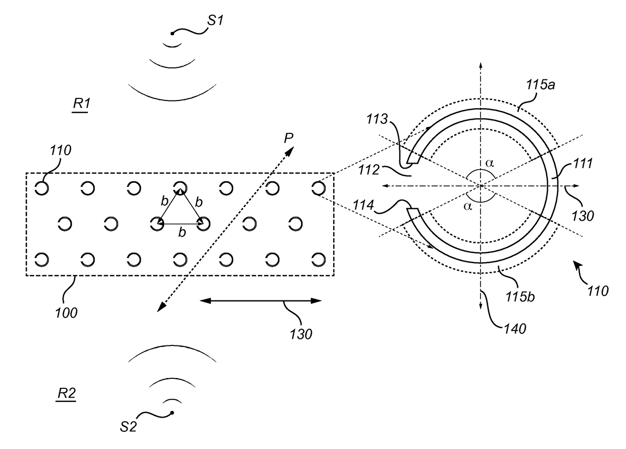
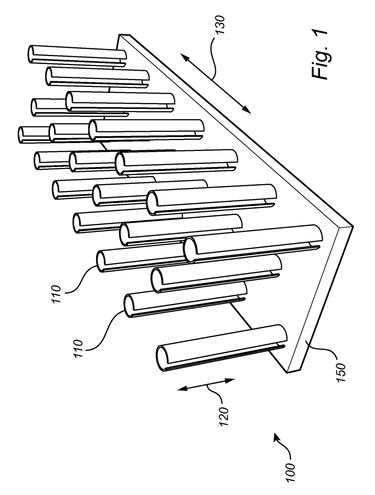
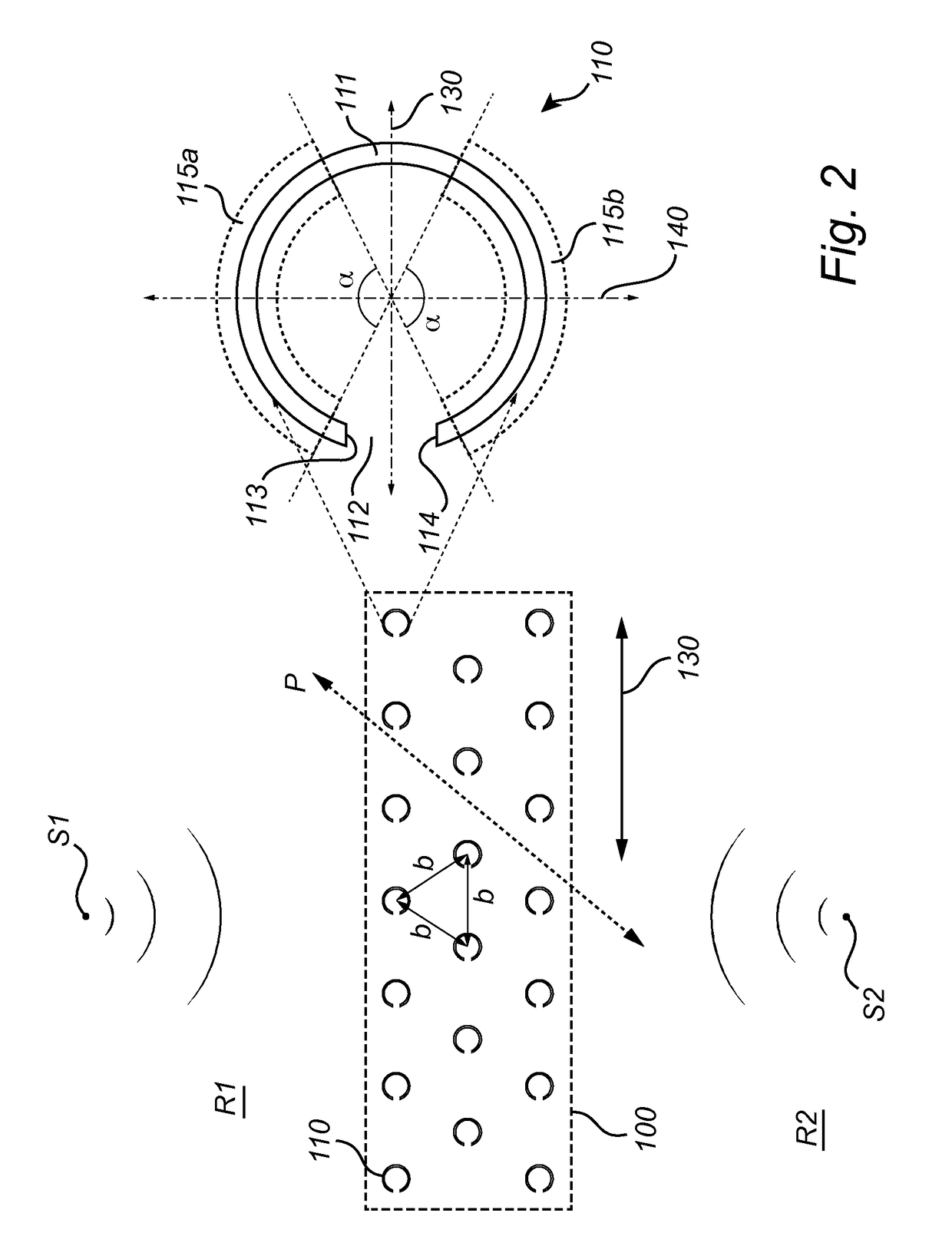
[0043]A room divider according to an embodiment will be described with reference to FIGS. 1 and 2. The room divider 100 is adapted to divide at least a portion of a room into two sub-portions R1, R2, and is adapted to attenuate sound S1, S2 travelling between the two sub-portions R1, R2. The room divider 100 comprises a plurality of hollow cylindrical elements 110 arranged periodically for dividing the portion of the room into the two sub-portions R1, R2. At least some of the hollow cylindrical elements 110 have a cylindrical shell 111 (s...


PUM


Abstract

A room divider (100) for dividing a room into two sub-portions (R1, R2) and for attenuating sound (S1, S2) travelling between the two sub-portions is provided. The room divider comprises hollow cylindrical elements (110) arranged periodically for dividing the room into the two sub-portions. At least some of the hollow cylindrical elements have a cylindrical shell (111) with at least one slit (112) extending in an axial direction (120) of the shell. The shell extends continuously along the perimeter of the corresponding hollow cylindrical element from one side (113) of the at least one slit to another side (114) of the at least one slit. Each of the at least one slit faces in a local elongation direction (130) of the room divider for increasing acoustic symmetry with respect to the two sub-portions. The use of destructive interference and resonance to attenuate sound allows for a less bulky / heavy acoustically absorbing room divider.

Description

CROSS-REFERENCE TO PRIOR APPLICATIONS[0001]This application is the U.S. National Phase application under 35 U.S.C. §371 of International Application No. PCT / EP2014 / 074289, filed on Nov. 11, 2014, which claims the benefit of European Application No. 13193296.4, filed on Nov. 18, 2013. These applications are hereby incorporated by reference herein.FIELD OF THE INVENTION[0002]The present invention generally relates to the field of acoustically absorbing room dividers.BACKGROUND OF THE INVENTION[0003]In open plan offices, people may have difficulties doing their job because of annoying and distracting sound around them. Such distraction may typically be caused by speech from other persons since in open plan offices speech may remain intelligible over large distances and may distract large groups of people. In order to reduce noise in open plan offices, acoustically absorbing / blocking room dividers may be placed between desks. Such room dividers may comprise acoustically absorbing materi...

Claims


Application Information

Patent Timeline
Patent Type & Authority Patents(United States)
IPC IPC(8): E04B1/82G10K11/172
CPCE04B1/8209G10K11/172
Inventor VAN DINTHER, CORNELUS HENDRICUS BERTUS ARNOLDUSAARTS, RONALDUS MARIAKOOIJMAN, GERBENOUWELTJES, OKKEKOHLRAUSCH, ARMIN GERHARDGOMMANS, HENDRIKUS HUBERTUS PETRUSVAN DORP SCHUITMAN, JASPER
Owner SIGNIFY HLDG BV
Why Eureka
Try Eureka