Adjustable rack

a rack and adjustable technology, applied in the field of adjustable racks, can solve the problems of not being able to adjust the height of the rack, and being unable to add more cradles to the existing gun rack,

Active Publication Date: 2017-10-10
KAHLE JAMES +1
View PDF94 Cites 5 Cited by
  • Summary
  • Abstract
  • Description
  • Claims
  • Application Information

AI Technical Summary

Problems solved by technology

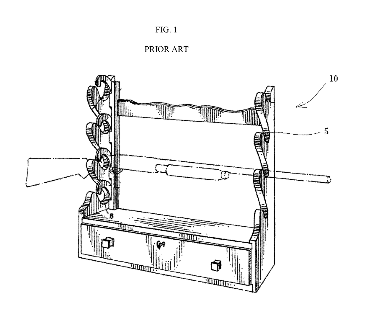
Thus, adding more cradles to an existing gun rack is generally not possible.
As yet another example, the positions of the cradles are typically fixed and do not allow for an adjustability of height.

Method used


Image

  • Adjustable rack
  • Adjustable rack
  • Adjustable rack

Examples


Embodiment Construction

[0023]Example embodiments will now be described more fully with reference to the accompanying drawings, in which example embodiments of the invention are shown. The invention may, however, be embodied in different forms and should not be construed as limited to the example embodiments set forth herein. Rather, these example embodiments are provided so that this disclosure will be thorough and complete, and will fully convey the scope of the invention to those skilled in the art. In the drawings, the sizes of components may be exaggerated for clarity.

[0024]In this application, it is understood that when an element or layer is referred to as being “on,”“attached to,”“connected to,” or “coupled to” another element or layer, it can be directly on, directly attached to, directly connected to, or directly coupled to the other element or layer or intervening elements that may be present. In contrast, when an element is referred to as being “directly on,”“directly attached to,”“directly con...


PUM


Abstract

Disclosed is an adjustable rack. In example embodiments, the rack may include a rail enclosing a nut used to fix a holder to the rail.

Description

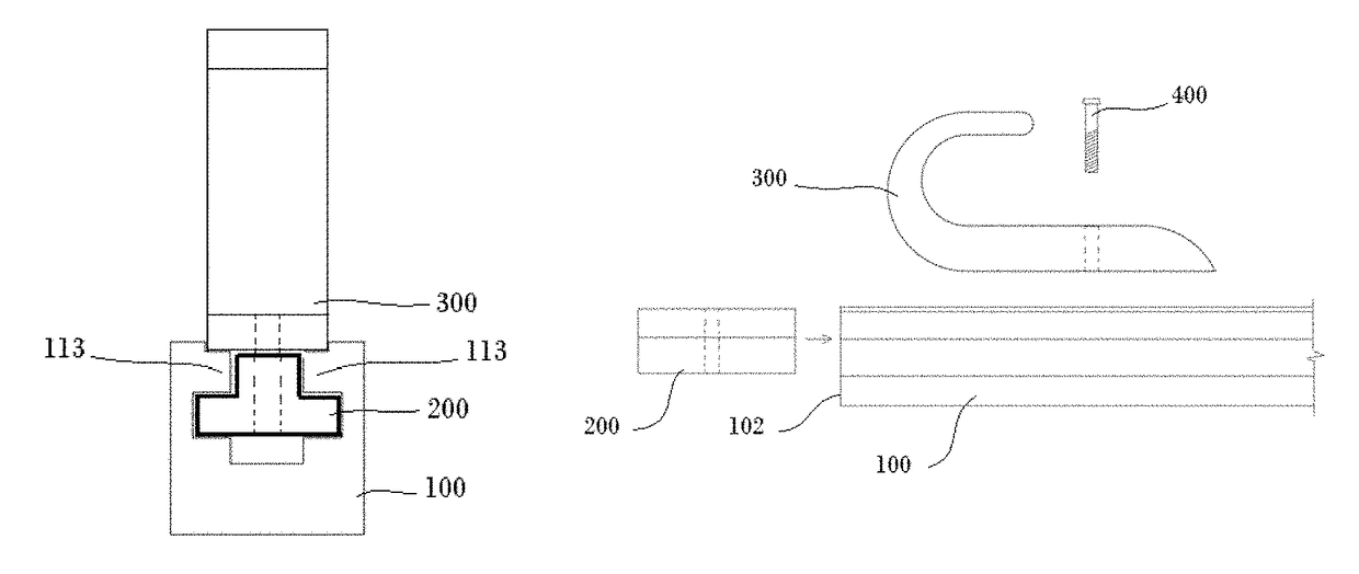
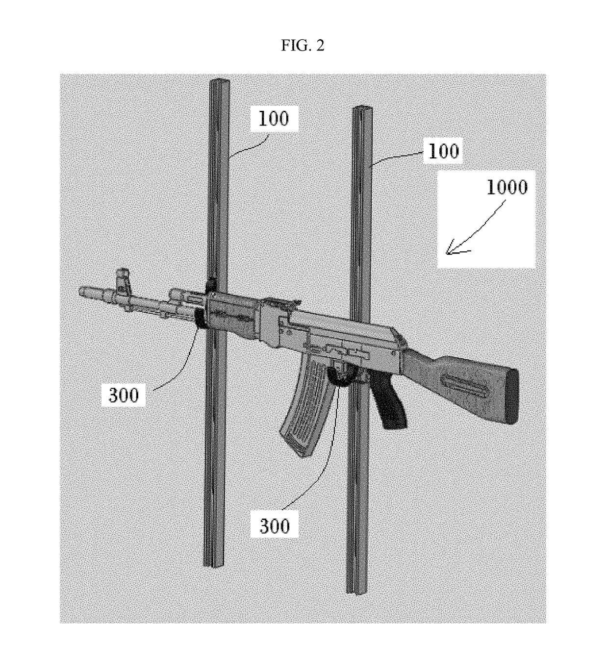
CROSS REFERENCE TO RELATED APPLICATIONS[0001]This application claims the benefit of U.S. Patent Application No. 62 / 165,382 filed with the United States Patent and Trademark Office on May 22, 2015, the entire contents of which are hereby incorporated by reference.BACKGROUND[0002]1. Field[0003]Example embodiments relate to an adjustable rack. In example embodiments, the rack may include a rail enclosing a connector used to fix a holder to the rail. In example embodiments the rack may have several uses, for example, supporting one or more guns.[0004]2. Description of the Related Art[0005]FIG. 1 is a view of gun rack 10 disclosed in U.S. Pat. No. 2,946,452. As shown in FIG. 1, the gun rack 10 includes cradles 5 for holding guns. Gun rack designs like the one shown in FIG. 1 are common in the market place. Such rack are easy to build and use.SUMMARY[0006]The inventors have noted that conventional gun racks, like that shown in FIG. 1, suffer several drawbacks. For example, they are typica...

Claims


Application Information

Patent Timeline
Patent Type & Authority Patents(United States)
IPC IPC(8): A47F5/08A47B96/14A47B81/00A47B96/06A47F5/00A47F5/10
CPCA47B81/005A47B96/06A47B96/1466A47F5/103A47F5/00A47F5/0846A47F5/08A47G25/06A47G25/0607A47G25/0614A47K10/12
Inventor KAHLE, JAMESKAHLE, MARY
Owner KAHLE JAMES
Why Eureka
Try Eureka