Striking tool with attached striking surface

a technology of striking surface and attachment, which is applied in the field of hammers with heads, can solve the problems of short life of tools, prior locking mechanisms, and the inability to permanently attach striking surfaces or allow replacement of striking surfaces, and other connecting methods that add significant costs

Active Publication Date: 2017-10-17
ESTWING MFG
View PDF112 Cites 3 Cited by
  • Summary
  • Abstract
  • Description
  • Claims
  • Application Information

AI Technical Summary

Problems solved by technology

However, such prior striking tools often relied on heavy construction that added to the weight of the striking tool or used malleable metal heads or striking surfaces, which led to short-lived tools.
Further, prior locking mechanisms, whether for permanent affixation of striking surfaces or that allowed striking surfaces to be replaced were not designed for long life.
In addition, other connecting methods added significant expense either in terms of the costs for materials and equipment required for affixation and / or in the added steps or energy required to carry out such methods.

Method used


Image

  • Striking tool with attached striking surface
  • Striking tool with attached striking surface
  • Striking tool with attached striking surface

Examples


Embodiment Construction

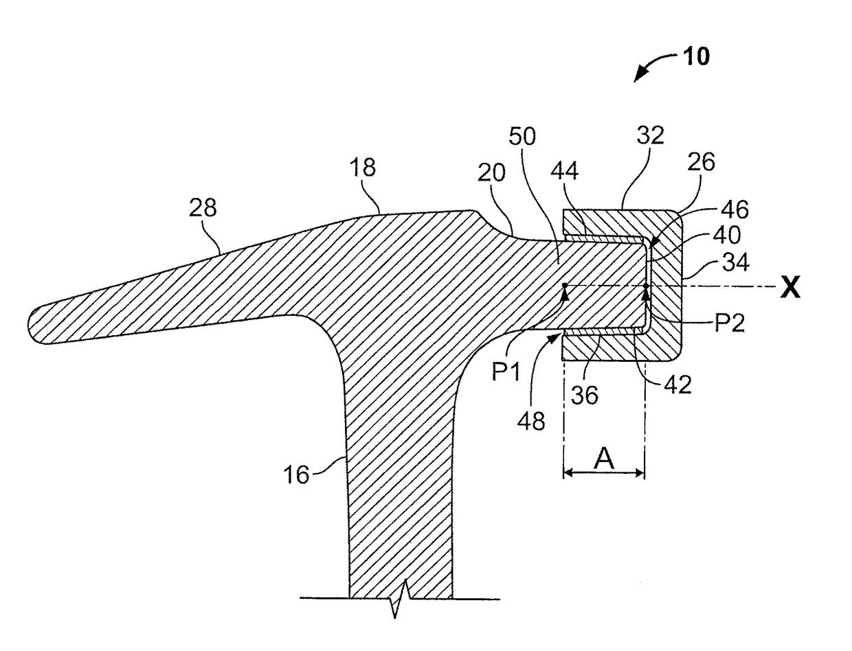
[0046]To overcome the deficiencies of the prior art, the present disclosure is directed to a striking tool 10 that adds to the concepts of FIGS. 1 and 1A and may be formed by attaching one or more striking surfaces to the head 18, which may be formed separately or from a single piece of material with the handle, by means including a pin, a threaded connection, shrink fitting, welding, brazing, adhesives, and the like. Herein, like structures are referred to with the same reference numbers. Furthermore, contemplated striking tools 10 may only include a subset of the features of striking tool 10 from FIGS. 1 and 1A and / or may include additional features.

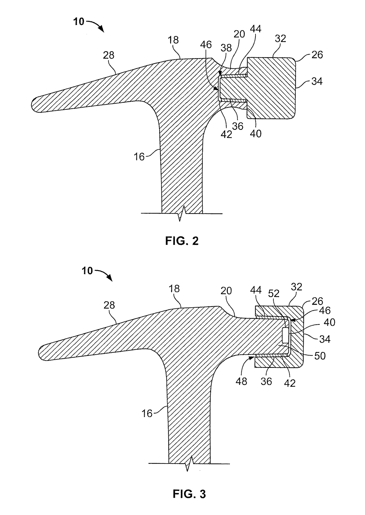
[0047]For example, in the embodiment of FIG. 2, a striking cap (cap) 32 is affixed to the head 18 of the striking tool 10. The cap 32 includes a striking surface 34 adapted for striking another surface (not shown), such as a fastener like a nail, spike, stake, staple, pin, or rivet. The striking surface 34 may also be appropriately sha...


PUM


Abstract

Striking tools are disclosed that include a handle and a head. Striking surfaces may be securely attached to the head. In this way, lighter weight striking tools may be made with greater durability.

Description

CROSS REFERENCE TO RELATED APPLICATIONS[0001]This application claims the benefit of U.S. Provisional Application Ser. No. 61 / 949,838, filed Mar. 7, 2014, which is incorporated herein by reference.REFERENCE REGARDING FEDERALLY SPONSORED RESEARCH OR DEVELOPMENT[0002]Not applicableSEQUENCE LISTING[0003]Not applicableBACKGROUND OF THE INVENTION[0004]1. Field of the Background[0005]The present invention relates generally to hammers with heads having a striking surface attached thereto, and more specifically, where the head and the striking surface may be different materials.[0006]2. Description of the Background[0007]As depicted in FIGS. 1 and 1A, a basic striking tool 10, for example, a claw hammer, includes a grip 12 disposed on a bottom section of a handle 14 that further includes a handle neck 16. Opposite of the grip 12 is a head 18. The head 18 includes a neck 20 and a poll 22 with a striking surface 24 having a beveled edge or chamfer 26. Opposite of the poll 22, a claw portion 28...

Claims


Application Information

Patent Timeline
Patent Type & Authority Patents(United States)
IPC IPC(8): B25D1/02B25D7/00B25D1/12
CPCB25D1/12B25D7/00B25D1/02B25D2250/051
Inventor WEST, JOSHUA D.FLOSI, STEVEN M.RYAN, JR., JOHN W.
Owner ESTWING MFG
Why Eureka
Try Eureka