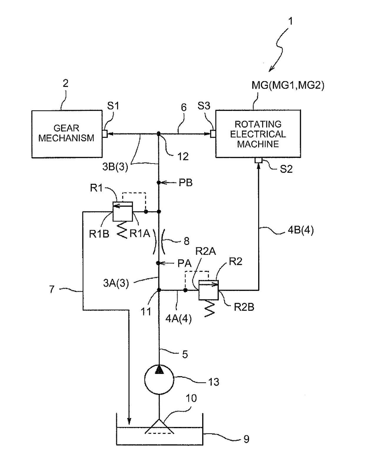
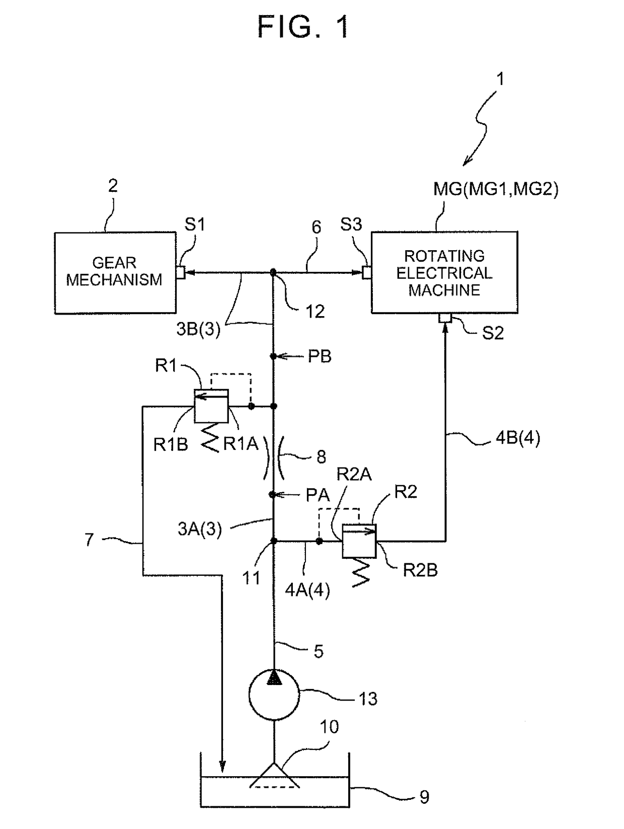
[0010]According to this characteristic configuration, since the oil pressure in the first oil passage is controlled to an oil pressure equal to or less than the first set oil pressure as an operation set pressure for the first relief valve, the flow rate of oil that is supplied to the gear mechanism is controlled to be in a proper range, and excessive oil supply to the gear mechanism can be suppressed. This can suppress an excessive increase in loss that is caused by the gear mechanism stirring oil when it rotates. The throttle portion is provided upstream of the first relief valve. Therefore, even in the state where the oil pressure in the first oil passage located downstream of the throttle portion is controlled to the first set oil pressure by the relief valve, the oil pressure in the oil passage located upstream of the throttle portion becomes higher than the first set oil pressure as a discharge pressure of the oil pump increases. Accordingly, the oil pressure in the second oil passage located upstream of the second relief valve also becomes higher than the first set oil pressure. The second relief valve having its operation set pressure set to the second set oil pressure higher than the first set oil pressure can thus be operated while controlling the oil pressure in the first oil passage located downstream of the throttle portion to the first set oil pressure. The flow rate of oil that is supplied to the gear mechanism can therefore be controlled to be in the proper range, and excess oil can be supplied to the rotating electrical machine via the second oil passage.
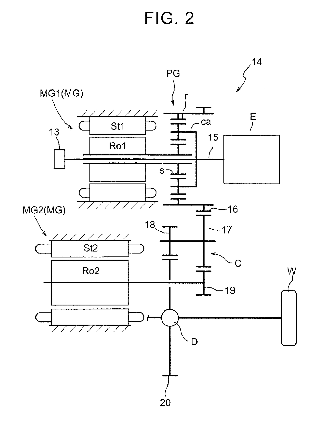
[0011]The oil pump is driven by the driving force source for the wheels. Accordingly, load on the rotating electrical machine that forms at least a part of the driving force source is also likely to be high when the oil pump has a high discharge pressure. According to the above characteristic configuration, the discharge pressure of the oil pump is increased and oil is supplied to the rotating electrical machine in a situation where the load on the rotating electrical machine is high and cooling or lubrication of the rotating electrical machine is particularly required. Therefore, oil can be appropriately supplied in a situation where there is a particularly strong need to supply oil to the rotating electrical machine. As described above, according to this characteristic configuration, an appropriate amount of oil can be supplied to both the gear mechanism and the rotating electrical machine by a simple configuration.
[0013]According to this configuration, oil discharged from the oil pump can be supplied to the rotating electrical machine sequentially via the common oil passage, the first oil passage, and the third oil passage in this order. That is, the oil discharged from the oil pump can be supplied to the rotating electrical machine via neither the second oil passage nor the second relief valve. Accordingly, oil can be steadily supplied to the rotating electrical machine even in a situation where the oil pump has a low discharge pressure and the load on the rotating electrical machine is likely to be low. In a situation where cooling or lubrication of the rotating electrical machine is particularly required, the discharge pressure of the oil pump is increased and the second relief valve is operated as described above, whereby a larger amount of oil can be supplied to the rotating electrical machine via the second oil passage and the second relief valve.
[0015]According to this configuration, at an oil pressure lower than such an upper limit oil pressure that the part having the lowest pressure resistance in the entire hydraulic circuit communicating with the common oil passage can withstand, the upstream side of the second relief valve is allowed to communicate with the downstream side of the second relief valve, so that oil is supplied to the rotating electrical machine. The oil pressure in the entire hydraulic circuit can thus be made not to exceed the upper limit oil pressure.
[0017]According to this configuration, communication between t upstream side of the second relief valve and the downstream side of the second relief valve can be suppressed in the case where the oil pressure in the first oil passage located downstream of the throttle portion is lower than the first set oil pressure, that is, when the first relief valve is not discharging oil in the first oil passage. The flow rate of oil that is supplied to the gear mechanism can therefore be controlled to be in the proper range, and excess oil can be supplied to the rotating electrical machine via the second oil passage.
[0019]According to this configuration, the first set oil pressure is set to an oil pressure in the predetermined range whose lower limit is the maximum required oil pressure. This can suppress oil supply to the gear mechanism at a flow rate that is too high with respect to the maximum flow rate required to lubricate the gear mechanism, and therefore can suppress loss that is caused by the gear mechanism stirring oil when it rotates.


