Heating cooker

a technology for cooking pots and cookers, applied in the field of cooking cookers, can solve the problems of large impact on the original flatness, lack of specific disclosure, and reduced visibility, so as to improve the thermal effect of the cooking container to be heated, reduce the effect of visibility and low heat resistan

Active Publication Date: 2018-01-09
PANASONIC INTELLECTUAL PROPERTY MANAGEMENT CO LTD
View PDF15 Cites 0 Cited by
  • Summary
  • Abstract
  • Description
  • Claims
  • Application Information

AI Technical Summary

Benefits of technology

[0014]An object of the present invention is to provide a high-design, low-cost, convenient heating cooker having a black-based top plate and a display device that uses light-emitting elements such as LEDs, capable of improving the reduction of visibility such as the display position differing (looking recessed in particular) depending on the viewing angle from the top plate upper surface and the restrictions (emitted light is shaded) on the structures arranged in the vicinity of the display device, as well as capable of reducing the thermal effect from the cooking container to be heated by spacing the display device apart from the top plate.
[0016]By virtue of this configuration, in a top plate of a heating cooker using a black-based top plate and in a display device using light-emitting elements such as LEDs, disposition of the diffusion region improves the reduction of visibility such as the display position differing (looking recessed in particular) depending on the viewing angle from the top plate upper surface and the restrictions (emitted light is shaded) on the structures arranged in the vicinity of the display device. More specifically, even in the case that ordinarily a shade appears inevitably when viewed from above from the positional relationship with the structures, the structures' shade is restrained from appearing since the user see the diffusion region. Furthermore, since the display device can be spaced apart from the top plate, the thermal effect from the cooking container to be heated is reduced so that the structures such as the light-emitting elements such as LEDs and the light guide used in this display device and the case of the display device can be formed of inexpensive materials with low heat resistance. Particularly, this is effective for equipment in which the cooking container to be heated is supposed to be placed above the light emitting device. Furthermore, use of the black-based top plate prevents the internal structures such as the display device and the heater element from being seen through during the non-heating (during non-light-emitting), enabling the provision of a high-design, low-cost, convenient heating cooker having both light-blocking properties and light-transmitting properties and presenting uniform color and flatness over the entire surface of the top plate when viewed from the top plate upper surface.
[0017]According to the heating cooker of the present invention, there can be implemented a top plate, esp. a black-based plate having both light-blocking properties and light-transmitting properties and having an excellent design without impairing the flatness, as well as a heating cooker superior in visibility for display of the state of heating.

Problems solved by technology

This type of heating cooker, however, embraces a program that the state of heating is hard to recognize, unlike the gas-operated cooker, etc., and therefore performs a display through various schemes using light-emitting elements such as LEDs or a liquid crystal display such as LCD arranged under the operation part or top plate.
The above prior art configuration, however, lacks a specific disclosure about the function to display the state of heating without impairing the design and visibility, such as having the viewing window without light-blocking layer, and has a possibility to impair the original flatness to a large extent.
This results in a problem for example that it is necessary for the structures such as the light-emitting elements such as LEDs and a light guide used in this display device and a case of the display device to be formed of expensive materials with high heat resistance.
There is also a problem that reduced visibility and uneven display may be inevitable depending on the position of the arrangement of the display device using the light-emitting elements such as LEDs, irrespective of blocking the portions other than the viewing window by the light-blocking layer as in the prior art document.
A problem is also present that since the color viewed from the top plate upper surface is different between the viewing window and the light-blocking layer, a uniform design surface cannot be formed over the entire surface of the top plate.
The above problems are remarkable in black-based top plates in particular.
Although the black-based top plates having a certain degree of light-blocking properties and light-transmitting properties are commercially available, use of them has not yet solved the details of the above problems at present.

Method used


Image

  • Heating cooker
  • Heating cooker
  • Heating cooker

Examples


first embodiment

[0048]FIGS. 1 to 5 are schematic views showing a schematic configuration, etc., of a heating cooker in a first embodiment of the present invention. It is to be noted that components unnecessary for description of the embodiment will be omitted even though they are main components. Hereinafter, description will be given by use of the drawings.

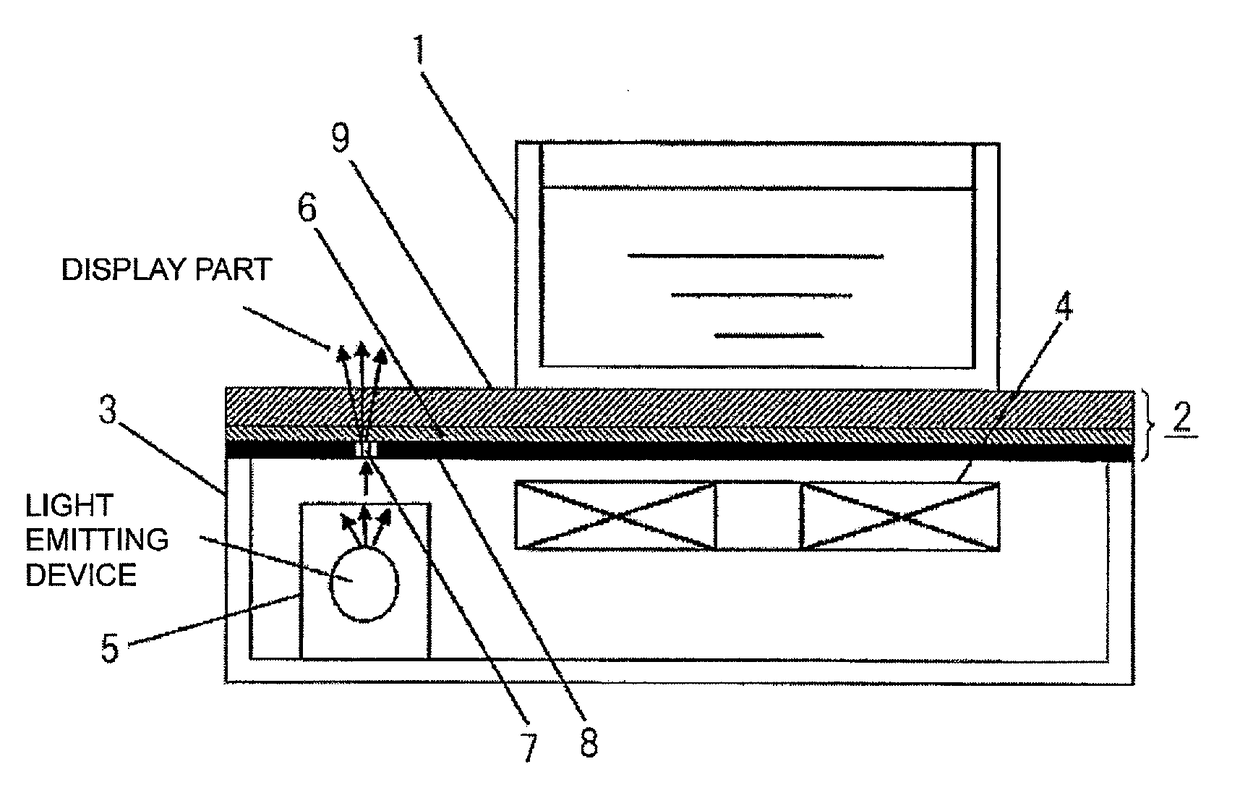
[0049]FIG. 1 is a schematic view showing the details of a heating cooker according to a first embodiment of the present invention. As shown in.FIG. 1, this heating cooker includes a top plate 2 on which a cooking container to be heated 1 is placed, an outer case 3 having an upper surface on which the top plate 2 is placed and making up a main body, a heater element 4 positioned below the top plate 2 to inductively heat the cooking container to be heated 1, and a display device 5 using light-emitting elements such as LEDs that display the heating state, etc., of the heater element 4.

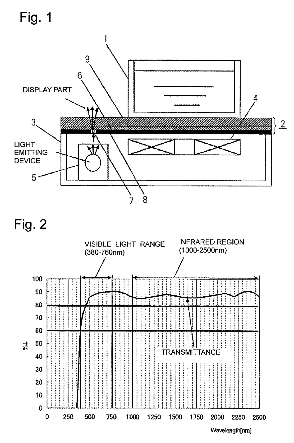
[0050]The top plate 2 has a light-transmitting low-expansion cry...

second embodiment

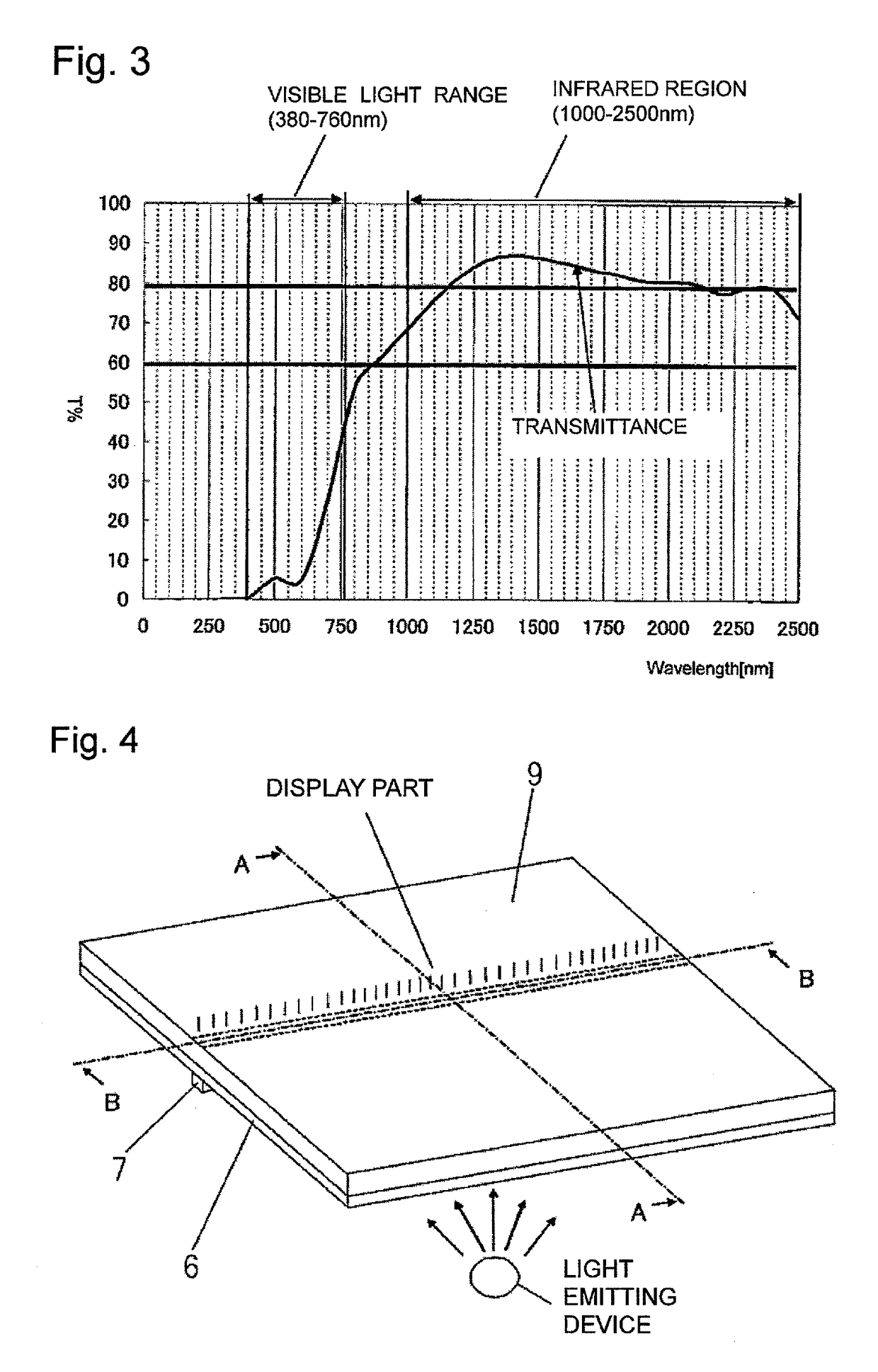
[0166]FIGS. 8 and 9 show a schematic configuration, etc., of a heating cooker according to a second embodiment of the present invention. In the second embodiment, the glass substrate 9 of the first embodiment was replaced by a black-based glass substrate 10. Some of component parts unnecessary for the description of the embodiment are not shown. Description will be made below with reference to the drawings.

[0167]Component parts similar to those of the first embodiment will repeatedly be described with reference to the same drawings.

[0168]Some of overlapping parts with the first embodiment will not be described.

[0169]FIG. 8 is a schematic view showing the details of the heating cooker according to the second embodiment of the present invention. As shown in FIG. 8, this heating cooker includes the top plate 2 on which the cooking container to be heated 1 is placed, the outer case 3 having an upper surface on which the top plate 2 is placed and making up the main body, the heater eleme...


PUM

PropertyMeasurementUnit
particle diameteraaaaaaaaaa
temperatureaaaaaaaaaa

Abstract

A heating cooker includes: a top plate on which a cooking container to be heated is placed; an outer case as a main body having an upper surface on which the top plate is placed; a heater heating the cooking container; and a light emitting device disposed in the outer case, for displaying the heating state. The top plate includes: a glass substrate having a transparent light-transmitting low-expansion crystallized glass made mainly of Li2O—AL2O3—SiO2 and having β-quartz solid solution, having a crystal size smaller than the wavelength of visible light; a design layer having a black-based color disposed on an undersurface of the glass substrate; a diffusion region disposed partially on an undersurface of the design layer, for diffusedly emitting light from the light emitting device; and a light-blocking layer disposed on the undersurface of the design layer other than the diffusion region, for blocking light from below.

Description

[0001]This application is a 371 application of PCT / JP2014 / 005588 having an international filing date of Nov. 6, 2014, which claims priority to JP 2013-230014 filed Nov. 6, 2013. The entire contents of these applications are incorporated herein by reference.BACKGROUND[0002]1. Technical Field[0003]This disclosure relates to a heating cooker for use on household dining table, countertop, sink, etc., or in business-use kitchen, etc., the heating cooker having a top plate on which a cooking container to be heated is placed. In particular, this disclosure relates to a heating cooker that heats the cooking container to be heated by a heater element disposed under the top plate, to perform cooking, the top plate having thereon a display indicative of the state of heating.[0004]2. Related Art[0005]Among this type of heating cookers, an IH cooker using an induction heating system for heating is becoming a recent mainstream and is popular in terms of its high safety and easy care. This by no m...

Claims


Application Information

Patent Timeline
Patent Type & Authority Patents(United States)
IPC IPC(8): F24C7/10F24C15/10F24C7/08C03C10/00C03C17/44C03C17/36
CPCF24C7/082C03C10/0027C03C17/3602C03C17/3684F24C15/106F24C7/083F24C15/10F24C15/102C03C17/44
Inventor AIHARA, KATSUYUKINAGATA, RYUUJISHICHI, KAZUYOSHI
Owner PANASONIC INTELLECTUAL PROPERTY MANAGEMENT CO LTD
Why Eureka
Try Eureka