
Hanger for mounting cables

a technology for mounting cables and hangers, which is applied in the direction of instruments, traffic signals, roads, etc., can solve the problems of affecting the service life of hangers,

Active Publication Date: 2018-01-09
COMMSCOPE TECH LLC
View PDF13 Cites 69 Cited by
  • Summary
  • Abstract
  • Description
  • Claims
  • Application Information

AI Technical Summary

Benefits of technology

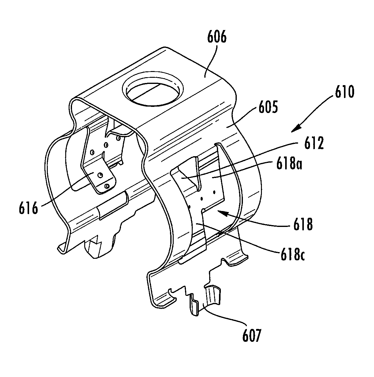
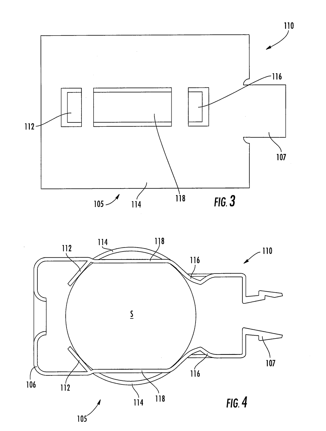
The invention is a cable hanger that is used to secure a cable to a structure with an aperture. It consists of a base panel, two arms, two locking projections, two flex members, and a cantilevered gripping member. The arms and locking projections are designed to spread apart to allow for easy insertion of a cable between them. The cantilevered gripping members engage and grip the cable, and the locking projections are designed to fit into the aperture of the structure. The technical effect of this invention is to provide a secure and easy-to-use way to attach cables to a supporting structure.

Problems solved by technology

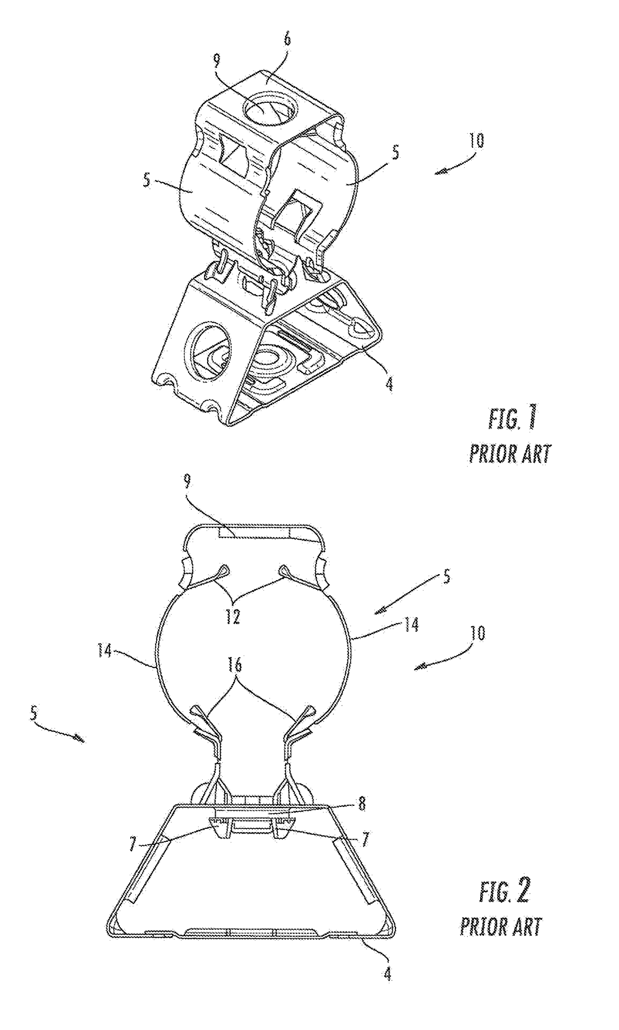
Antenna towers and or tunnels may be crowded due to the large numbers of cables required for signal-carrying.
This arrangement has been suitable for use with coaxial power cables, which tend to be manufactured in only a few different outer diameters; however, the arrangement has been less desirable for fiber optic cables, which tend to be manufactured in a much greater variety of diameters.
Moreover, fiber optic cables tend to be much heavier than coaxial cables (sometimes as much as three times heavier per unit foot), which induces greater load and stress on the hangers.

Method used


Image

  • Hanger for mounting cables
  • Hanger for mounting cables
  • Hanger for mounting cables

Examples


Embodiment Construction

[0032]The present invention is described with reference to the accompanying drawings, in which certain embodiments of the invention are shown. This invention may, however, be embodied in many different forms and should not be construed as limited to the embodiments that are pictured and described herein; rather, these embodiments are provided so that this disclosure will be thorough and complete, and will fully convey the scope of the invention to those skilled in the art. It will also be appreciated that the embodiments disclosed herein can be combined in any way and / or combination to provide many additional embodiments.

[0033]Unless otherwise defined, all technical and scientific terms that are used in this disclosure have the same meaning as commonly understood by one of ordinary skill in the art to which this invention belongs. The terminology used in the below description is for the purpose of describing particular embodiments only and is not intended to be limiting of the inven...


PUM


Abstract

A cable hanger includes: a base panel having opposed ends; a pair of arms, each of the arms attached to a respective end of the base panel and having a free end; a pair of locking projections, each of the locking projections attached to a respective free end of the arms; and a pair of gripping members, each gripping member attached to a respective arm, each gripping member having opposed ends, wherein one of the ends of each gripping member is fixed to the arms and the other of the ends of each gripping member is fixed to the arm or to the base panel. The arms and locking projections are configured to spread apart to enable insertion of a cable between the arms, wherein the gripping projections engage and grip the cable, and wherein the locking projections are configured to be inserted into the aperture of the supporting structure.

Description

RELATED APPLICATION[0001]This application claims priority from and the benefit of U.S. Provisional Patent Application Nos. 62 / 139,057, filed Mar. 27, 2015; 62 / 206,558, filed Aug. 18, 2015; and 62 / 248,460, filed Oct. 30, 2015, the disclosures of which are hereby incorporated herein by reference in their entirety.FIELD OF THE INVENTION[0002]invention relates generally to devices for supporting cables and, in particular, to hangers for securing cables to support structures.BACKGROUND OF THE INVENTION[0003]Cable hangers are commonly used to secure cables to structural members of antenna towers and or along tunnel walls. Generally, each cable is attached to a structural member by cable hangers mounted at periodically-spaced attachment points.[0004]Antenna towers and or tunnels may be crowded due to the large numbers of cables required for signal-carrying. Over time, as systems are added, upgraded and / or expanded, installation of additional cables may be required. To conserve space, it ma...

Claims


Application Information

Patent Timeline
Patent Type & Authority Patents(United States)
IPC IPC(8): F16L3/00H02G3/32F16B1/00
CPCF16B1/00H02G3/32F16B2/243F16B5/0685E01F9/608E01F9/65G09F15/0018G09F15/0037G09F15/0062G09F15/0075G09F23/00
Inventor VACCARO, RONALD A.JOSHI, AVIRALRAJPAL, TAIG S.
Owner COMMSCOPE TECH LLC
Learn More