
Clamp and method of use

a technology of clamps and clamshells, applied in the field of clamps, can solve the problems of many screen printing press operators experiencing fatigue and minor injuries, requiring many expensive parts, and many users experiencing production lag, so as to achieve the effect of quick screen replacemen

Active Publication Date: 2018-01-23
JURMAN GARY PAUL
View PDF11 Cites 10 Cited by
  • Summary
  • Abstract
  • Description
  • Claims
  • Application Information

AI Technical Summary

Benefits of technology

The invention is a clamp that is easy to use for changing screens on a screen printing press. It allows for quick actuation and quick release with a minimal amount of pressure. This clamp can be attached to a screen printing press to quickly change out screens without the need for re-registration.

Problems solved by technology

Because of the number of manipulations of the clamps required during press setup and operation, many screen printing press operators experience fatigue and minor injuries during setup.
When changing between multiple screens, the user experiences production lag due to the excessive motion required to release and actuate the clamps.
There are several drawbacks of such systems: 1) they require many expensive parts, including a compressor, 2) they take up excessive space, 3) they require electricity, and 4) they are unwieldy to use on a carousel press, a commonly used design for multicolor screen printing presses.
Problems caused by such use are 1) the angle of the actuating mechanisms for various hand-tool lock clamps is not suitable for ease of use with screen printing presses because they are ergonomically shaped to be used with a different orientation to the body than what is practical for affixing them to screen printing presses; 2) the release of hand-tool lock clamps is “all or nothing” and often jars the screen upon release, causing it to shift position, in turn further spoiling registration, 3) the grip of many lock clamps is designed for “all or nothing” clamping, making it difficult for screen registration when the operator desires a loose grip prior to full engagement, 4) lock clamps with variable pressure may not be easily fully engaged with a single action, and the pressure can not be loosened without fully disengaging, 5) the action of many lock clamps creates a non-perpendicular force during grip, causing the workpiece or screen to slip when being engaged.

Method used


Image

  • Clamp and method of use
  • Clamp and method of use
  • Clamp and method of use

Examples


Embodiment Construction

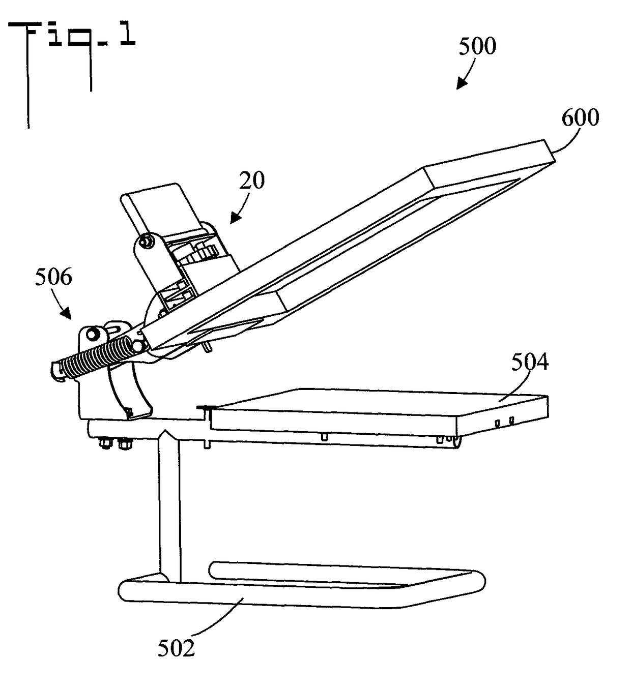
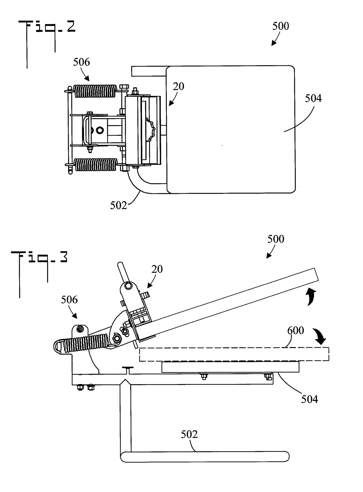
[0053]Referring initially to FIG. 1, there is illustrated a reduced perspective view of a screen printing press 500 having a clamp 20 which holds a screen 600. FIG. 2 is a reduced top plan view of screen printing press 500 without screen 600. And, FIG. 3 is a reduced side elevation view of screen printing press 500, clamp 20, and screen 600. As shown, screen printing press 500 includes a base 502, a platen 504 for supporting a substrate to be printed such as a tee-shirt (not shown), and clamp 20 for removably holding screen 600. Clamp 20 is pivotally connected to base 502 by a pivot mechanism 506, and can be placed in the raised position of FIGS. 1 and 3, or in a lowered ready-for-printing position wherein screen 600 is adjacent platen 504 (shown in dashed lines in FIG. 3). Clamp 20 is removably connectable to pivot mechanism 506.

[0054]FIGS. 4 and 5 are perspective views of clamp 20 in an open position and a closed position respectively, and FIG. 6 is a reduce exploded perspective v...


PUM


Abstract

A clamp includes a fixed jaw assembly which has a fixed jaw and a movable jaw assembly which has a movable jaw. The movable jaw assembly is movable with respect to said fixed jaw assembly so that the movable jaw moves with respect to the fixed jaw. A handle is rotatably connected to the fixed jaw assembly, the handle includes a cam which moves the movable jaw assembly. When the handle is placed in a first rotational position the jaws are open and the movable jaw is disposed a first distance from the fixed jaw. When the handle is placed in a second rotational position the jaws are closed and the movable jaw is disposed a second distance from the fixed jaw, the second distance being less than the first distance. An adjustment is provided for changing both the first and second distances.

Description

CROSS REFERENCE TO RELATED APPLICATION[0001]This application claims the filing benefit under 35 U.S.C. § 119(e) of U.S. Provisional Application No. 61 / 940,530, filed Feb. 17, 2014, which is hereby incorporated by reference.TECHNICAL FIELD[0002]The present invention relates generally to clamps which are utilized to clamp a workpiece, and more particularly to a clamp which is opened and close by the rotation of a handle.BACKGROUND OF THE INVENTION[0003]Clamps are well know in the art. In one application, screen printing presses use a clamp system to hold their screens in register. It is common for press operators to continually release and reapply the clamps multiple times in order to achieve correct positioning of the screens. Because of the number of manipulations of the clamps required during press setup and operation, many screen printing press operators experience fatigue and minor injuries during setup. It would be desirable to have a device which clamps with minimal operator ex...

Claims


Application Information

Patent Timeline
Patent Type & Authority Patents(United States)
IPC IPC(8): B41F15/36B25B1/08B25B1/24F16M11/04
CPCB41F15/36B25B1/2489B25B1/08F16M11/041B25B5/02B25B5/06B25B5/08B25B5/10F16M13/022
Inventor JURMAN, GARY PAUL
Owner JURMAN GARY PAUL
Learn More