Fluid transfer connection

a technology of transfer connection and flue gas, which is applied in the direction of intravenous devices, catheters, infusion needles, etc., to achieve the effects of convenient use, convenient use, and convenient us

Active Publication Date: 2018-02-13
CONCEPTOMED AS
View PDF48 Cites 1 Cited by
  • Summary
  • Abstract
  • Description
  • Claims
  • Application Information

AI Technical Summary

Benefits of technology

[0036]While the lever member may take many different forms, preferably the lever member comprises a front surface that is substantially transverse to the axis of the tip and the front surface is arranged to move along the tip when the lever member is pivoted against the resilient bias. In order for the lever member to transfer force efficiently, it is preferable for it to be relatively stiff. However it may also be desirable to mould the device, or at least the lever member, from plastics materials so as to provide a cheap, sterile and disposable product for single use in a medical setting. The lever member may be stiffened by forming it as a three-dimensional shell. Preferably the lever member comprises a front surface that is substantially transverse to the axis of the tip and one or more side surfaces that extend in a direction substantially parallel to the axis of the tip. Preferably the surfaces form a shroud extending back from the front surface and away from the fluid transfer tip. The three-dimensional extent of the member can help to ensure that it is stiff even if formed of a plastics material, as is preferred in various embodiments.
[0037]In a set of embodiments the lever member has an at least partially cylindrical form with the side surface(s) extending substantially parallel to the axis of the fluid transfer tip being cylindrical side surfaces. The side surface(s) do not need to fully surround the axis of the fluid transfer tip. But in at least one set of embodiments the front surface of the lever member is connected to one or more side surfaces that surround the fluid transfer tip. This can stiffen the lever member so that the front surface preferably does not flex when pushed against a hub but instead transmits its kinetic energy to move the hub away.
[0038]Alternatively, or in addition, the front and side surface(s) of the lever member are preferably integrally formed. For example, at least these parts of the lever member may be formed as a single plastics moulding. Alternatively, or in addition, it is preferable that the front surface at least partially surrounds the fluid transfer tip. The front surface may entirely surround the fluid transfer tip, for example with the tip protruding through an aperture in the front surface. This can make the lever member more compact and / or make the front surface more effective in pushing against a hub mounted on the fluid transfer tip with a friction fit.
[0039]A further advantage of using a lever member to disconnect the hub is that the shape, in particular the curvature, of the front surface can be designed to control the leverage that is achieved. In one set of embodiments the front surface is curved such that initial movement of the lever member (e.g. against a resilient bias) moves the front surface substantially transverse to the fluid transfer tip to release engagement of the screw fit and further movement of the lever member (e.g. against the resilient bias) moves the front surface along the fluid transfer tip to release the hub from the friction fitting. Accordingly the curvature of the front surface provides for two different movements that are matched to the different stages of disconnection.

Problems solved by technology

Simply releasing the screw fit is not enough to disconnect the hub from the fluid transfer tip; the hub can not fall away from the tip under gravity due to the friction fitting.

Method used


Image

  • Fluid transfer connection
  • Fluid transfer connection
  • Fluid transfer connection

Examples


Embodiment Construction

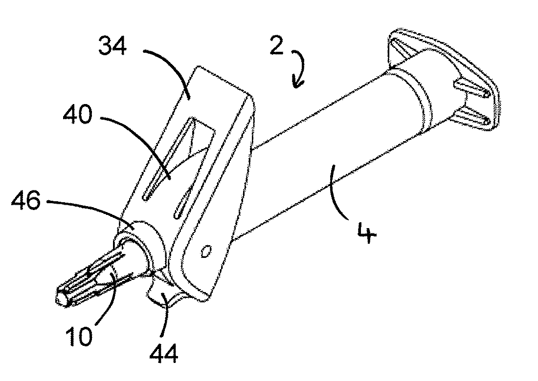
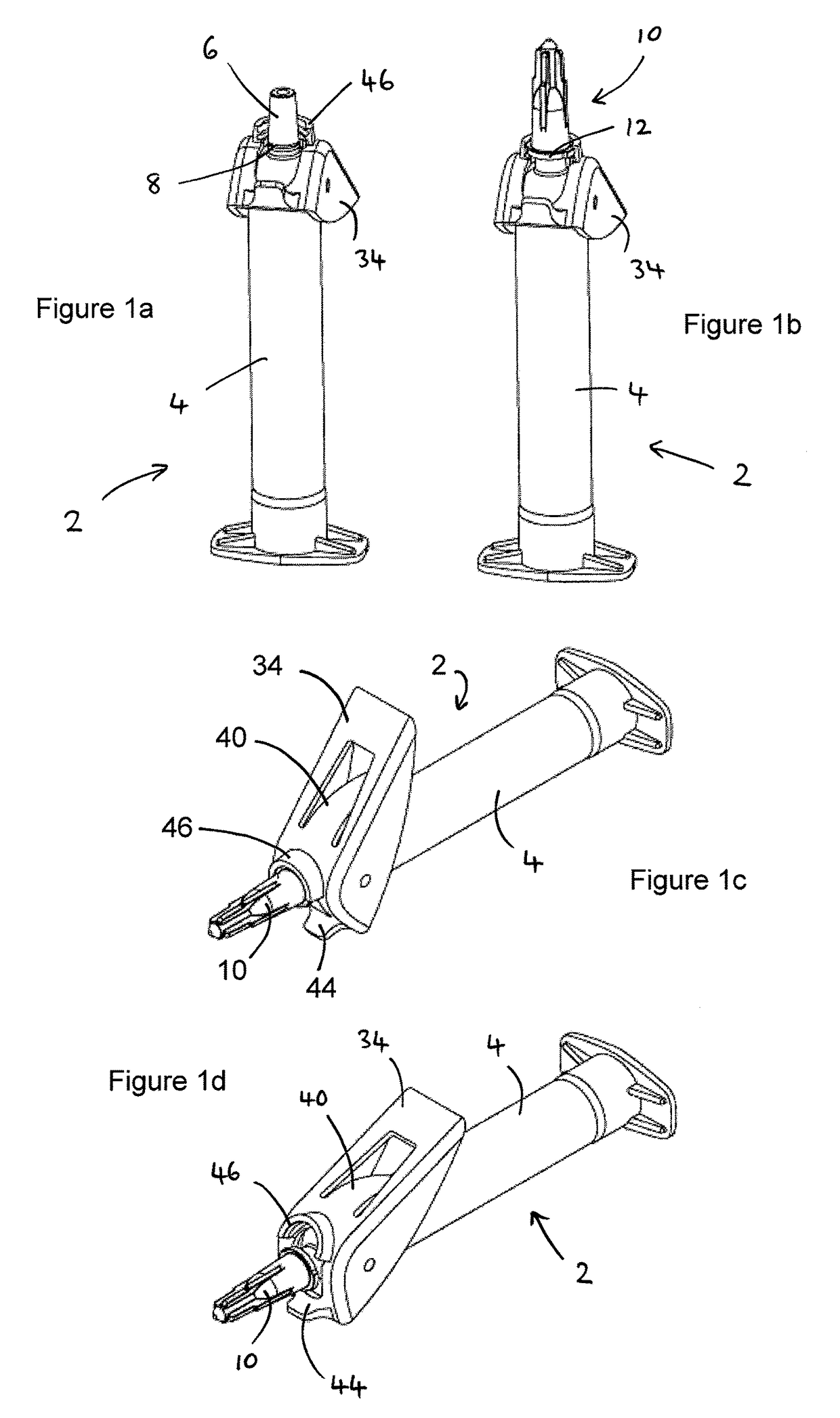
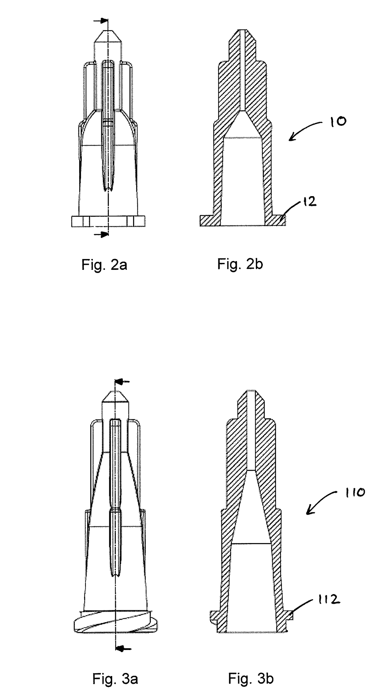
[0080]FIGS. 1a to 1d illustrate an embodiment of a disconnecting mechanism for a hub 10. The syringe 2 has a fluid transfer tip 6 that is tapered so as to form a Luer slip connection i.e. friction fitting with a corresponding hub 10. In addition the tip 6 may optionally be provided with an annular gripping flange 8 surrounding the tip 6 close to the barrel 4 of the syringe 2. The hub 10 may be a standard Luer slip hub 10 as seen in FIGS. 2a and 2b, or a hub 410 as seen in FIGS. 14a and 14b which includes an annular groove on its inner surface to grip onto the flange 8. The hub 10 may be similar to a standard Luer slip hub having an internal taper and an outer rim 12, except additionally provided with a skirt extending below the rim 12. Alternatively, the hub 10 may be a standard Luer lock hub 110 as seen in FIGS. 3a and 3b.

[0081]In this embodiment (see FIG. 1a) the syringe 2 has a pivotally mounted lever member 34 which carries a forwardly extending latch 46 in the form of a partia...


PUM


Abstract

A fluid transfer device or connection with a fluid transfer tip that has a tapered friction fitting for a corresponding hub. A lever member is pivotally mounted to move relative to the fluid transfer tip. A latch such as a screw thread is mounted on the lever member to engage the hub and provide a positive connection e.g., screw fit in addition to the friction fitting. The lever member may optionally be resiliently biased by a spring. The hub is disconnected from the tip by pivoting the lever member to release the positive connection with the hub and to subsequently release the hub from the friction fitting.

Description

TECHNICAL FIELD[0001]The present invention relates to the detachment of fluid-transferring devices and connections from a corresponding hub, and especially when transferring fluid in a medical setting. The invention may find particular use in detaching a fluid transfer device such as a syringe, or other fluid transfer connection, from a hub that is connected to a living subject to / from whom fluid is being transferred.BACKGROUND OF THE INVENTION[0002]In a medical setting it may be necessary or desirable to transfer fluid to / from a subject for a variety of reasons. For example, a hub connected to a needle or other cannula may be used to draw blood from a vein or to infuse fluid substances i.e. intravenous (IV) therapy. A drip is one type of IV therapy. IV therapy may be used to correct electrolyte imbalances, to deliver medications or nutrition, for blood transfusion or as fluid replacement to correct dehydration. IV therapy can also be used for chemotherapy of cancer patients. Fluid-...

Claims


Application Information

Patent Timeline
Patent Type & Authority Patents(United States)
IPC IPC(8): A61M25/16A61M5/34A61M25/18A61M5/32A61M5/31
CPCA61M5/3134A61M5/3205A61M5/347A61M5/346A61M2005/3206A61M2005/3142A61M5/344A61M5/32
Inventor MIDE, CHRISTIANANDRESEN, MARIUSBLOMVAGNES, ROLFGEERS, KEVIN
Owner CONCEPTOMED AS
Why Eureka
Try Eureka