
Ink jet recording device and density unevenness correction method therefor

a recording device and density unevenness technology, applied in the direction of printing, power drive mechanisms, printing mechanisms, etc., can solve the problems of density unevenness, density unevenness is rather worse, and land interference changes, so as to achieve high-quality images and correct density unevenness

Active Publication Date: 2018-02-27
FUJIFILM CORP
View PDF9 Cites 2 Cited by
  • Summary
  • Abstract
  • Description
  • Claims
  • Application Information

AI Technical Summary

Benefits of technology

[0044]According to the invention, in the ink jet recording device in which the medium supporting part is supported by the supports having the comb teeth structure, the density unevenness can be corrected appropriately, and a high-quality image can be drawn.

Problems solved by technology

As a result, the following problems occur.
If the variation occurs in the temperature distribution of the entire medium, even in a case where the same amount of ink droplets are dropped, the diameter of dots changes, the degree of landing interference changes, or density unevenness occurs.
However, since related-art density unevenness correction is a method of outputting a test chart to obtain a correction value required for correction of the density unevenness, the following problems occur if this method is applied.
That is, since the temperature distribution occurring in the medium is not uniform as a whole, if the related-art technique is applied as it is, there is a problem that the density unevenness is rather worsened.

Method used


Image

  • Ink jet recording device and density unevenness correction method therefor
  • Ink jet recording device and density unevenness correction method therefor
  • Ink jet recording device and density unevenness correction method therefor

Examples


modification example

of Second Method

[0351]A density unevenness correction value of each region can also be obtained in the following procedure.

[0352]First, a temporary density unevenness correction value for each grayscale is obtained from the reading result of the test chart TC. This temporary density unevenness correction value includes the influence of the paper supporting part 110.

[0353]Next, the temporary density unevenness correction value is Fourier-transformed, and is decomposed into a plurality of frequency components.

[0354]Next, the fundamental frequency ω1 and the frequency component of the integral multiple of the fundamental frequency ω1 are removed from the data after the Fourier transform.

[0355]Next, the data after the fundamental frequency ω1 and the frequency component of the integral multiple of the fundamental frequency ω1 are inverse-Fourier-transformed. Accordingly, the correction value of the density unevenness for correcting the main density unevenness component is obtained. This...


PUM


Abstract

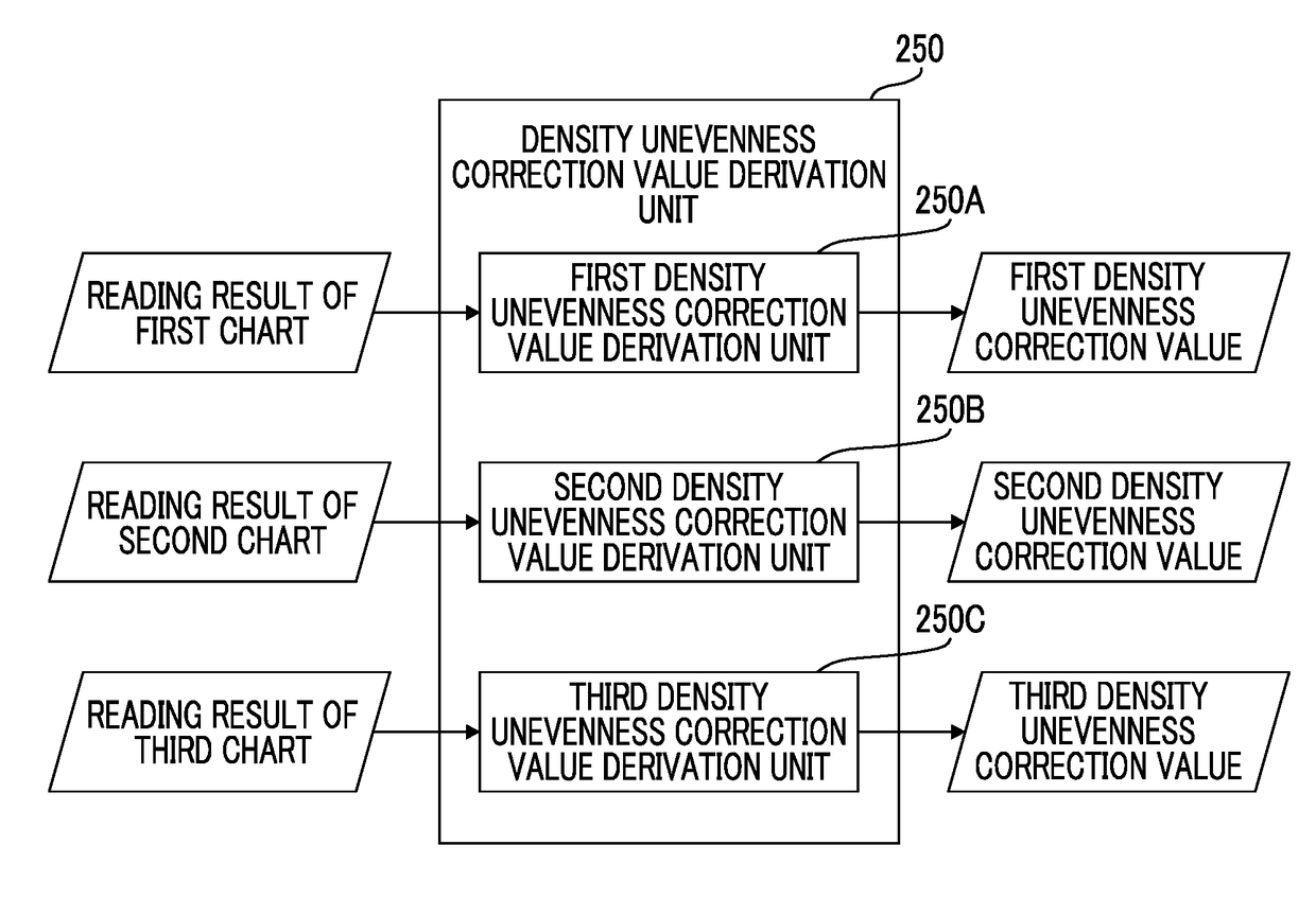
In an ink jet recording device in which a paper supporting part is constituted by a first support and a second support having a comb teeth structure, a region where paper is supported by only the first support is defined as a first region, a region where the paper is supported by only the second support is defined as a second region, and a region where the paper is supported by the first support and the second support is defined as a third region. Charts including a plurality of grayscales for the respective regions are drawn. The respective drawn charts are read by an image reader. Correction values of density unevenness are obtained for the respective regions on the basis of the reading results. Density data of an image are corrected for the respective regions on the basis of the correction values of the density unevenness for the respective regions.

Description

CROSS-REFERENCE TO RELATED APPLICATIONS[0001]The present application claims priority under 35 U.S.C. § 119 to Japanese Patent Application No. 2016-077268, filed on Apr. 7, 2016. The above application is hereby expressly incorporated by reference, in its entirety, into the present application.BACKGROUND OF THE INVENTION1. Field of the Invention[0002]The present invention relates to an ink jet recording device and a density unevenness correction method therefor.2. Description of the Related Art[0003]Drum transportation is known as one of methods for transporting media in ink jet recording devices. The drum transportation is a method for winding a medium around a peripheral surface of a rotating drum to transport the medium.[0004]A drum in which a supporting part for a medium is extendable and retractable is described in JP2010-149417A. In this drum, the supporting part for the medium is constituted by a pair of supports having a comb teeth structure. The comb teeth structure is a stru...

Claims


Application Information

Patent Timeline
Patent Type & Authority Patents(United States)
IPC IPC(8): B41J11/057B41J29/393B41J13/22B41J2/21
CPCB41J29/393B41J2/2132B41J2/2139B41J2/2146B41J11/057B41J13/223B41J2/2142B41J2029/3935B41J2025/008
Inventor YAMANOBE, JUN
Owner FUJIFILM CORP
Learn More