
Image forming apparatus and image quality adjusting method

a technology of image quality and forming apparatus, applied in the field of image forming apparatus, can solve the problems of lowering the reproducibility of images, toner deposition, and uneven density of electrostatic charging characteristics, and achieve the effect of quick correction of density unevenness, less toner consumption, and improved reproducibility

Active Publication Date: 2018-10-16
SHARP KK
View PDF4 Cites 0 Cited by
  • Summary
  • Abstract
  • Description
  • Claims
  • Application Information

AI Technical Summary

Benefits of technology

[0007]It is an object of the present invention to provide an image forming apparatus and an image quality adjusting method capable of quickly correcting the effect of density unevenness in a rotational direction of an image bearing member.
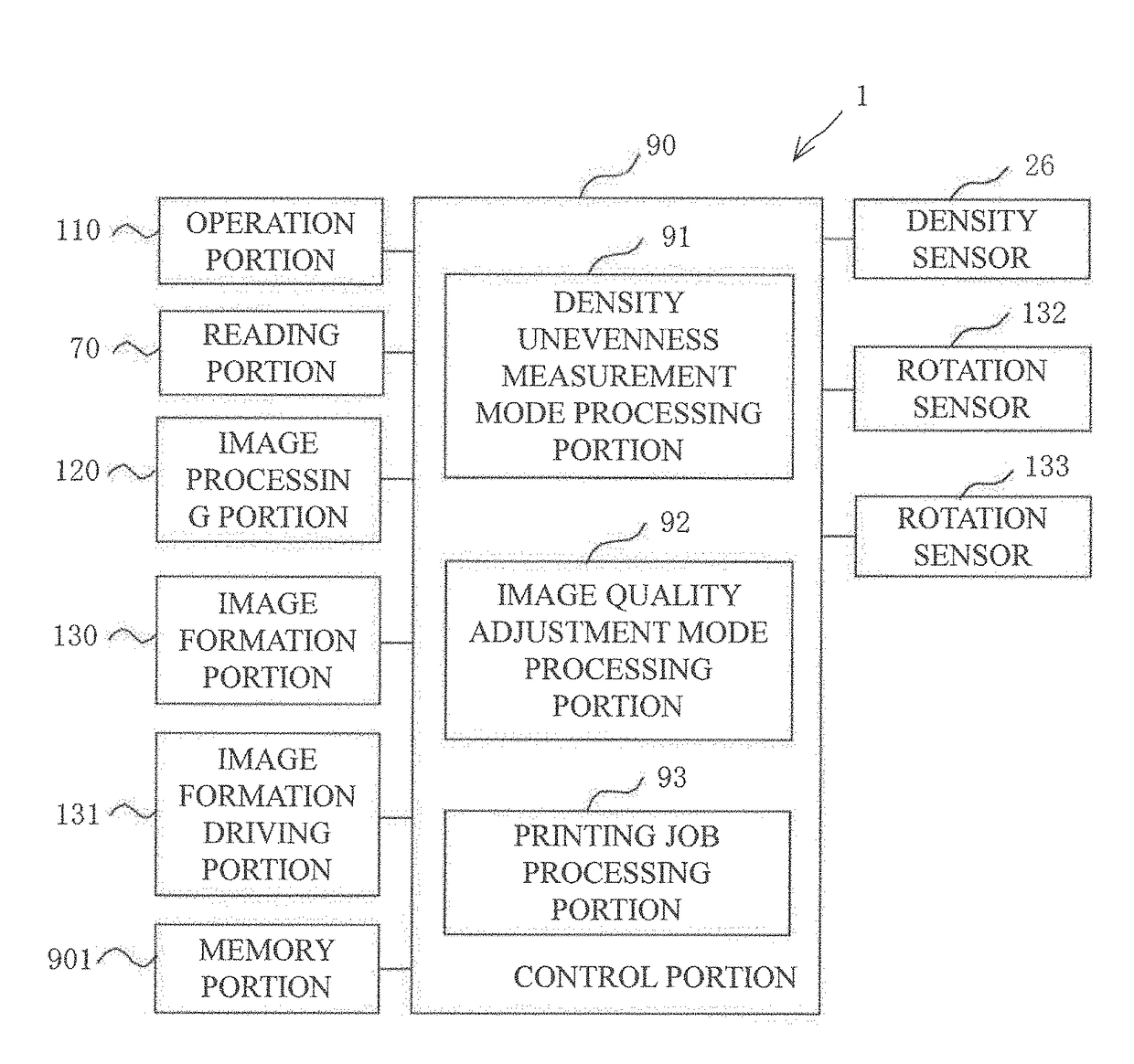
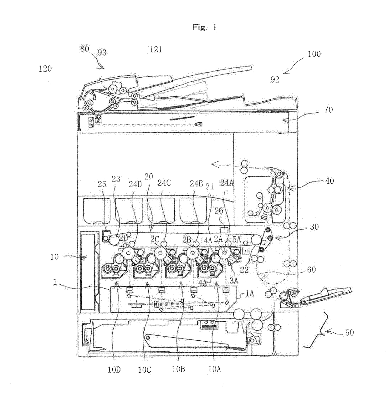
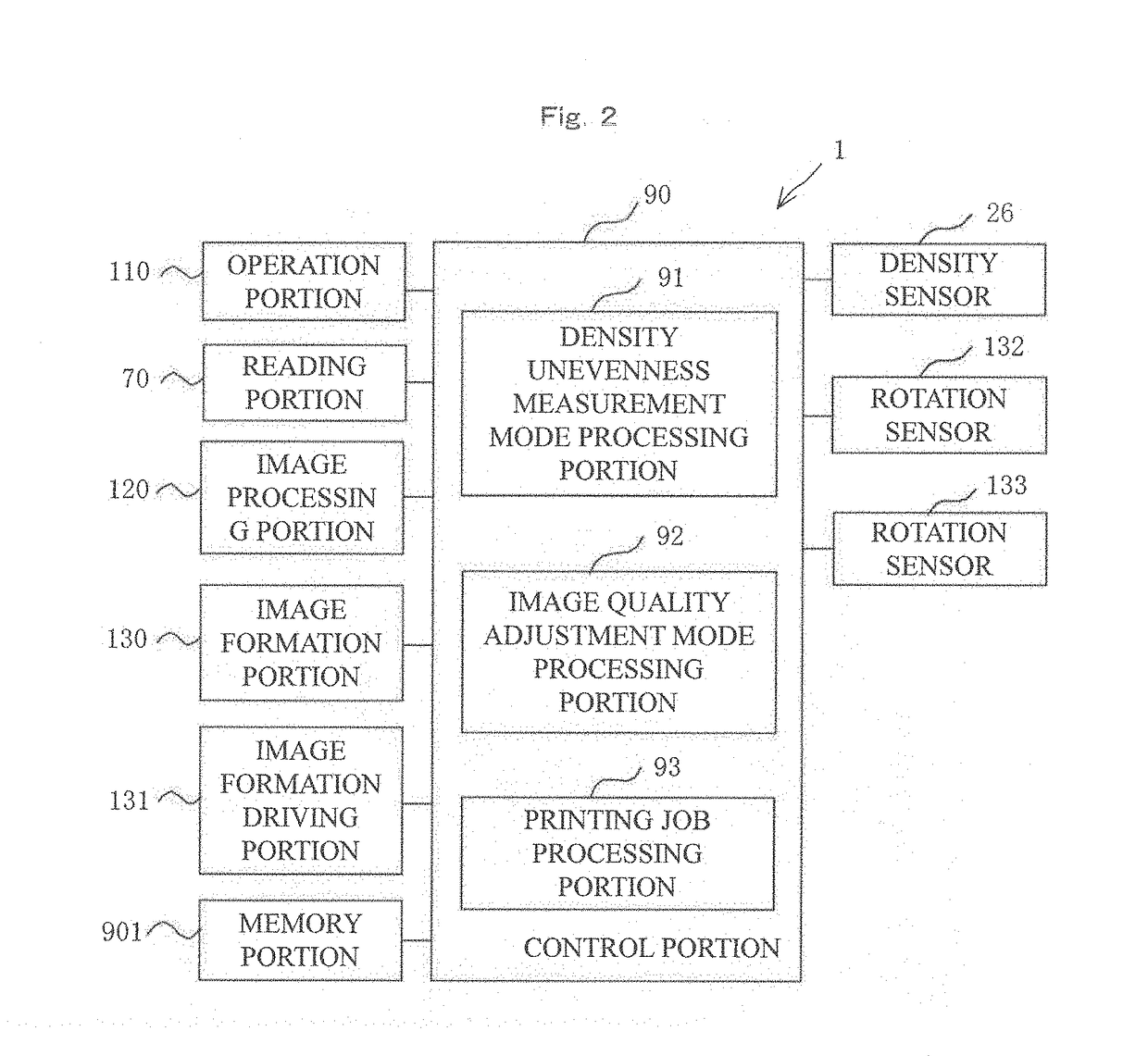
[0010]According to these inventions, at the time when the image bearing member was mounted (including replaced and mounted again) onto the apparatus main body, all density information in the sub-scanning direction which is the rotational direction of the image bearing member is detected being associated with the rotation phase of the image bearing member, and detected density information is stored beforehand in the memory portion being associated with the rotation phase of the image bearing member. Subsequently, at the time of the image quality adjustment, the image quality adjustment toner image is formed at any position in the rotational direction of the image bearing member with a quick timing, that is, without waiting for a specific rotation phase position to come, and density of the image quality adjustment toner image that has been formed is detected at the rotation phase. Then, the density of the image quality adjustment toner image that has been detected is corrected based on the density information that is associated with a rotation phase that matches a rotation phase at which the density of the image quality adjustment toner image has been detected among said density information that has been captured in the memory portion. Therefore, the present invention makes it possible to quickly correct the density unevenness in the sub-scanning direction of the image bearing member with a less toner consumption, and to further perform the image quality adjustment with higher accuracy.

Problems solved by technology

If mechanical misalignment or a change such as eccentricity and / or the like occurs in a revolving shaft of the image bearing member, distance from the surface of the image bearing member changes in a sub-scanning direction which is rotational direction, and thus unevenness may occur in electrostatic charging characteristics, amount of laser light and toner deposition characteristics.
Such mechanical misalignment or a change results in a change of toner deposition amount that is finally deposited onto the image bearing member, thereby lowering the reproducibility of images.
However, in the image forming apparatus described in JP 2012-230312A, it is necessary to decide the arrangement of the patches on the image bearing member depending on the period which is the determination result, and thus, at the time of an image quality adjustment, it is necessary to wait until the position decided on the image bearing member revolves to come to a position that is faced by the density sensor; therefore, there is a problem that doing so takes a time.
Accordingly, the time needed to perform an entire image quality adjustment becomes longer.
Moreover, in the case of color, because there are four colors, for each of which it is necessary to adjust a phase, the time needed to perform an overall positional adjustment cannot be ignored.
Besides, because the image bearing member has to be revolved more to that extent, there is also a problem that its service life becomes shortened.

Method used


Image

  • Image forming apparatus and image quality adjusting method
  • Image forming apparatus and image quality adjusting method
  • Image forming apparatus and image quality adjusting method

Examples


second embodiment

[0042]FIGS. 8A, 8B are diagrams explaining a FIGS. 8A, 8B show a case where a cause of the density unevenness occurring in the sub-scanning direction lies with the developing roller (magnetic roller) 41 of the developing unit 4 as well, in addition to the photoreceptor drum 2. Here, as in FIG. 5, the density unevenness is shown exaggeratedly for convenience of description. In a case such as where the revolving shaft of the developing roller 14 is not parallel with the surface of the photoreceptor drum 2, there may arise an oscillation in the performance of supplying the toner onto the photoreceptor drum 2 in the rotational direction (sub-scanning direction) of the developing roller 14, and may thereby cause the occurrence of the density unevenness on the photoreceptor drum 2. In such a case, it is necessary to tackle the density unevenness in phase in a sub-scanning direction synthesized from the photoreceptor drum 2 and the developing roller 14 that revolve synchronously with each...

third embodiment

[0044]Further, instead of the embodiment where the density detection is performed on the intermediate transfer belt 21 side, as a third embodiment, an embodiment where direct density detection is performed with the density sensor 2 disposed at each photoreceptor drum 2 may be acceptable. This makes it possible to perform the process without being affected by the intermediate transfer belt 21.

[0045]Additionally, the above-mentioned embodiments can be implemented to each color in the same manner.


PUM


Abstract

An image forming apparatus includes: a density unevenness measurement mode processing portion that, in a density unevenness measurement process, detects density of a density unevenness measurement toner image, which has been formed in a rotational direction of the photoreceptor drum, multiple times in the rotational direction and captures in a memory portion all detected density information associating thereof with rotation phases of the photoreceptor drum; and an image quality adjustment processing portion that, in an image quality adjustment mode, detects density of an image quality adjustment toner image, which has been formed at any position in the rotational direction of the photoreceptor drum, in the rotational direction and corrects detected density information based on density information associated with a rotation phase matching a rotation phase where density of the image quality adjustment toner image has been detected among said all density information having been captured in the memory portion by the density unevenness measurement processing portion.

Description

CROSS REFERENCE[0001]This Nonprovisional application claims priority under 35 U.S.C. § 119(a) on Patent Application No. 2016-086469 filed in Japan on Apr. 22, 2016, the entire contents of which are hereby incorporated by reference.BACKGROUND OF THE INVENTION[0002]The present invention relates to an image forming apparatus such as copier, multi-functional apparatus, laser printer, facsimile and so forth that performs image forming according to the electrophotography method, and to an image quality adjusting method.[0003]In an image forming apparatus, density of a toner image that is deposited onto a revolving image bearing member may change caused by a change of environment such as temperature and / or humidity, and / or a change over time and so forth. Therefore, where necessary, density adjustment for a gradation correction is performed by carrying out a process control, that is, by forming a test pattern consisting of multiple patches sequentially in different levels of toner density ...

Claims


Application Information

Patent Timeline
Patent Type & Authority Patents(United States)
IPC IPC(8): G03G15/00
CPCG03G15/5058G03G15/5041G03G2215/00075G03G15/5033G03G15/5008
Inventor UCHIDA, HIROHISA
Owner SHARP KK
Learn More