Connector

a technology of connecting rods and connectors, applied in the direction of coupling device connection, securing/insulating coupling contact members, electrical apparatus, etc., can solve the problems of retaining members, retaining members may not be pushed, and workers may forget to push parts of retaining members, so as to reduce time and labor required for assembly operation, enhance the reliability of the connection of the connector, and enhance the efficiency of the connector assembly operation

Inactive Publication Date: 2007-10-16
YAZAKI CORP
View PDF11 Cites 34 Cited by
  • Summary
  • Abstract
  • Description
  • Claims
  • Application Information

AI Technical Summary

Benefits of technology

[0034]In the invention of claim 2, when the distal end of the retaining member abuts against the second slanting portion, the worker can feel this abutting condition through the hand, and a click feel is obtained upon provisional retaining of the retaining member, and the retaining member can be positively provisionally retained. And besides, since the distal end of the retaining member abuts against the second slanting portion, the retaining member is prevented from being accidentally shifted into the completely-retained condition by interference with the exterior or the like, and the insertion of the terminals can be accurately effected in the provisionally-retained condition of the retaining member.
[0035]In the invention of claim 3, the provisionally-retained condition of the retaining member relative to the connector housing is maintained, and therefore the operation for inserting the terminals into the connector housing can be effected accurately.
[0036]In the invention of claim 4, the completely-retained condition of the retaining member relative to the connector housing is firmly maintained, and therefore the retained condition of the terminals is prevented from being accidentally canceled, and the reliability of the connection of the connector (the electrical connection of the terminals to mating terminals) is enhanced.
[0037]In the invention of claim 5, the operations for provisionally retaining the plurality of retaining members, as well as the operations for completely retaining the plurality of retaining members, can be effected simultaneously by sliding the holder. Therefore, as compared with the case where the worker pushes a plurality of retaining members into a connector housing with the hand so as to provisionally and completely retain the retaining members, the efficiency of the connector assembling operation is more enhanced, and also the time and labor required for the assembling operation are reduced.
[0038]In the invention of claim 6, the terminals are retained in a triple manner by the retaining lances, the protruding portions (for preventing the bending of these lances) and the retaining member, and the withdrawal of the terminals is positively prevented, and the reliability of the connection of the connector is enhanced. And besides, an improper insertion of any terminal in the connector housing is detected by the protruding portion, so that the reliability of the connection of the connector is further enhanced.
[0039]In the invention of claim 7, even in the case where another kind of terminals are received within the connector housing, these terminals are firmly retained by the corresponding retaining lances and the corresponding protruding portions of the holder, and therefore the reliability of the connection of the connector is enhanced.

Problems solved by technology

However, in the conventional connector 81 of FIG. 15, the upper and lower terminals inserted in the connector housing and primarily retained by the respective retaining lances 84 must be retained in a secondary manner by pushing the upper and lower retaining members 85 one by one into the connector housing, and therefore there has been encountered a problem that much time and labor are required for the secondary retaining of the terminals.
And besides, there has been a fear that the worker may forget to push part of the retaining members 85 for secondarily retaining purposes.
It is feared that this problem arises particularly in the case where a plurality of retaining members 85 are provided at the upper side or the lower side of the connector housing 82.
Also, even in the case the terminals of the same kind are used such that the terminals in the upper terminal receiving chambers 83 and the terminals in the lower terminal receiving chambers are not inverted relative to each other, but are disposed in the same posture, there has been encountered a problem that the retaining members 85 can not be properly disposed, so that the double retaining of the terminals can not be effected.

Method used


Image

  • Connector
  • Connector
  • Connector

Examples


first embodiment

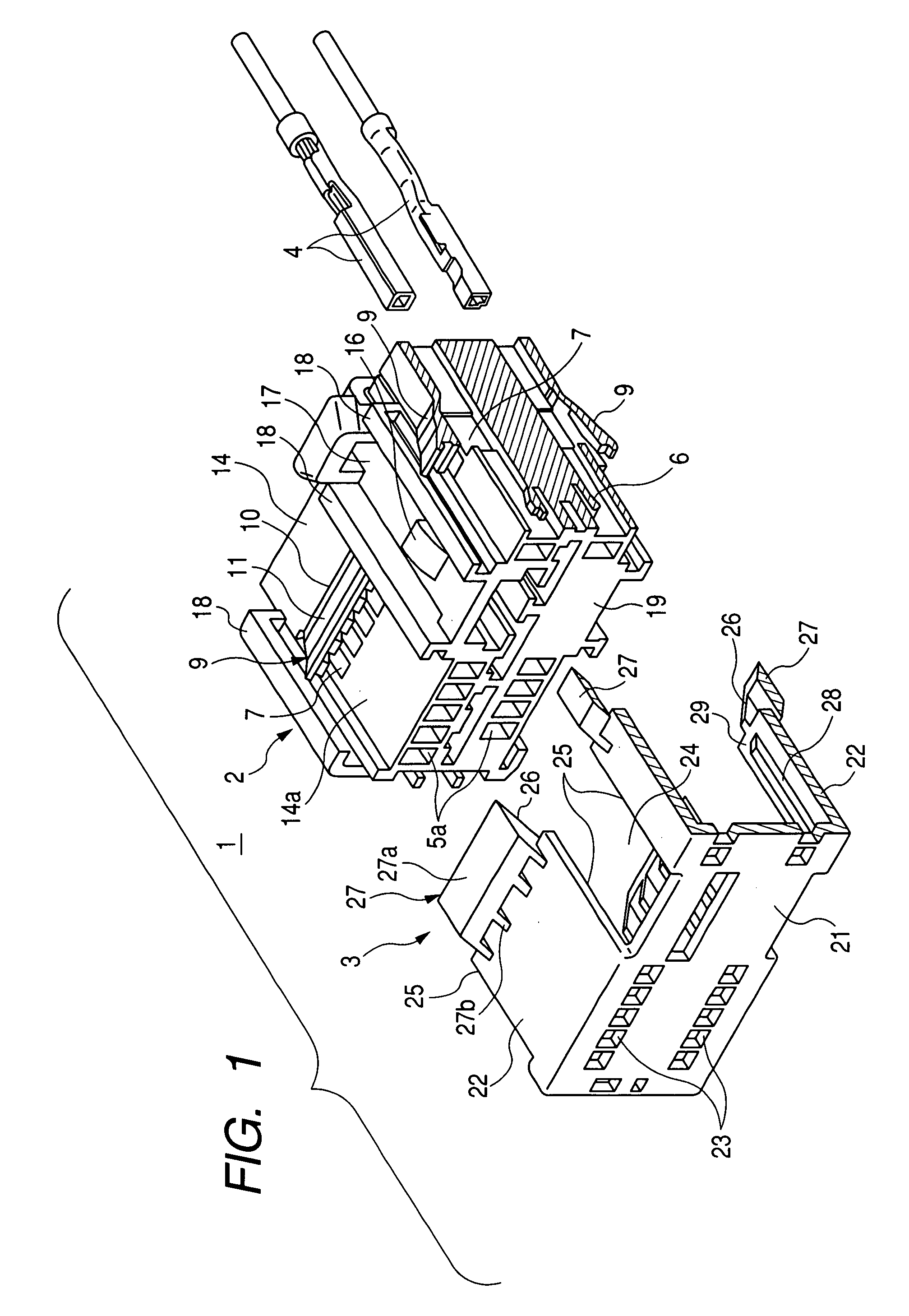
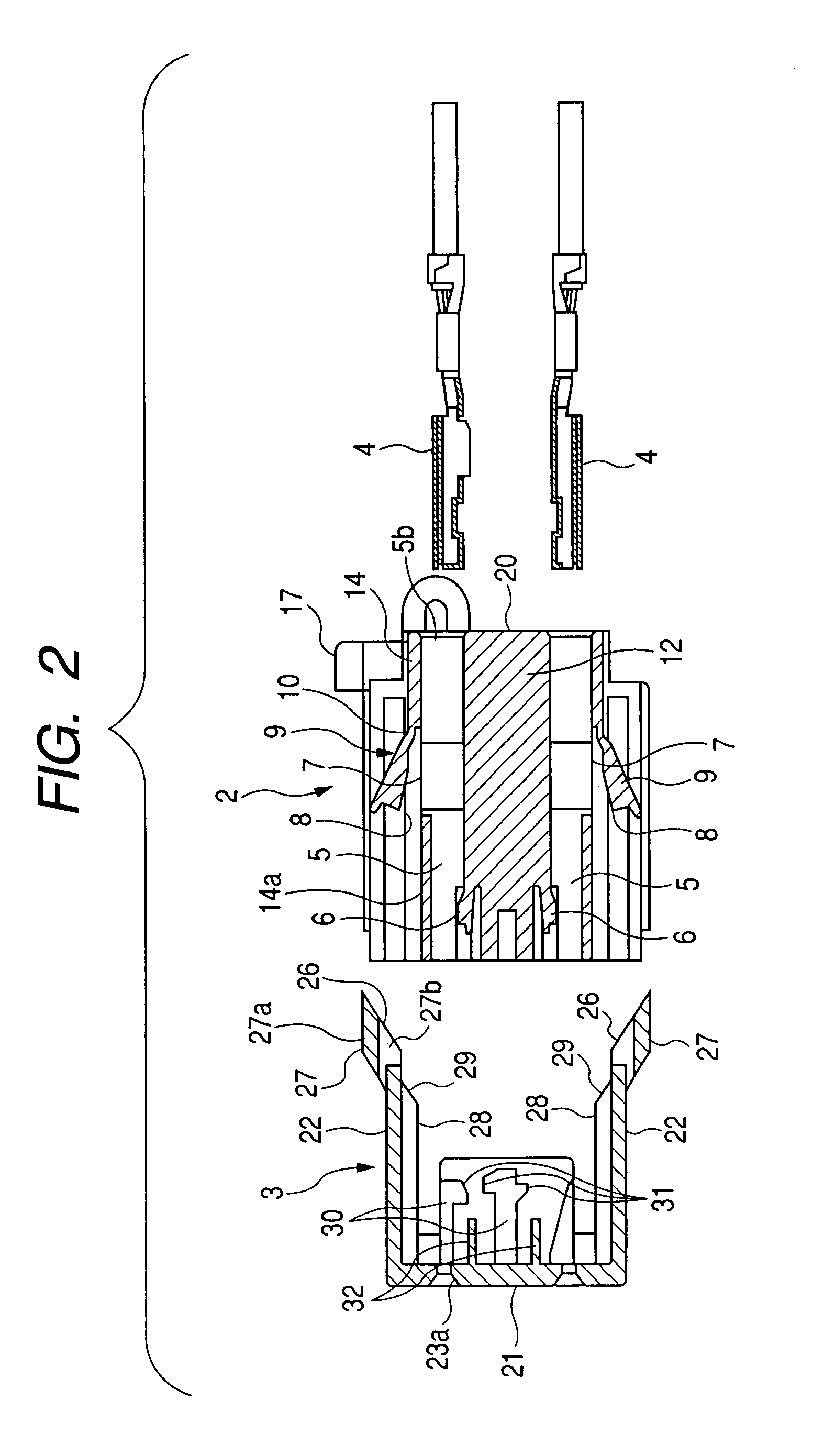
[0056]FIGS. 1 to 4 show a connector of the present invention.

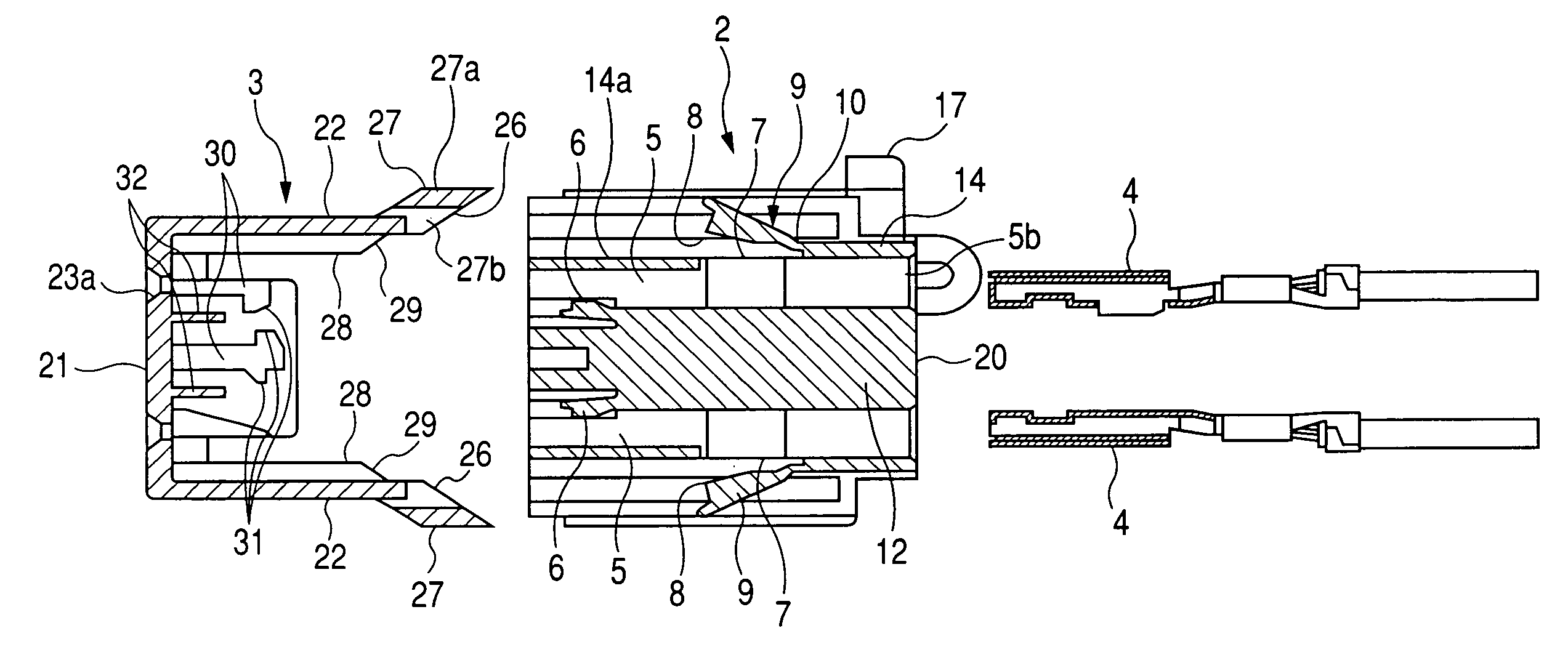
[0057]As shown in FIGS. 1 and 2, this connector 1 comprises a synthetic resin-made connector housing 2, a synthetic resin-made front holder 3 attached to the connector housing 2 from a front side thereof toward a rear side thereof, and female terminals 4 (each having a wire connected thereto) inserted into the connector housing 2 from the rear side thereof.

[0058]The connector housing 2 has terminal receiving chambers 5 (FIG. 2) arranged in two (upper and lower) rows, and the female terminals 4 are received respectively in the upper and lower terminal receiving chambers 5 in such a manner that the upper female terminals 4 and the lower female terminals 4 are disposed symmetrically (that is, in generally back-to-back relation). First elastic arm-like terminal retaining lances 6 are provided respectively at front half portions of the upper and lower terminal receiving chambers 5 in such a manner that the upper retaining lance...


PUM


Abstract

To positively retain terminal retaining members provisionally and completely relative to a connector housing, a connector 1, 41, 61 includes a connector housing 2, 42, 62 for receiving terminals 4, 64, and a holder 3, 43, 63 attached in a sliding manner to the connector housing. Terminal retaining members 9 are pivotally provided respectively at opening portions 7 of the connector housing. The holder includes first slanting portions 26 for pushing the terminal retaining members into the respective opening portions so as to provisionally retain the terminal retaining members, and second slanting portions 29 for further pushing the terminal retaining members into the opening portions so as to completely retain the terminal retaining members. When the retaining members are provisionally retained, a distal end of each retaining member abuts against the corresponding second slanting portion. The plurality of retaining members are provided, and the plurality of first slanting portions, as well the plurality of second slanting portions, are provided in corresponding relation to the plurality of retaining members, respectively.

Description

BACKGROUND OF THE INVENTION[0001]1. Field of the Invention[0002]This invention relates to a connector in which terminals within a connector housing are retained by retaining lances and retaining members in a double manner, and the bending of the retaining lances are prevented by protruding portions of a front holder.[0003]2. Description of the Related Art[0004]FIG. 15 shows one conventional connector (see Patent Literature).[0005]This connector 81 comprises a connector housing 82 made of a synthetic resin, and terminals 100 (each having a wire connected thereto) inserted in respective terminal receiving chambers 83 of the connector housing 82. Elastic lances 84 for primarily retaining purposes and retaining members 85 for secondarily retaining purposes are provided at the connector housing 82, and each retaining member 85 is provided so as to be pivotally moved about a hinge formed at a rear end thereof.[0006]The retaining member 85 has a provisionally-retaining step portion 87 and ...

Claims


Application Information

Patent Timeline
Patent Type & Authority Patents(United States)
IPC IPC(8): H01R13/514
CPCH01R13/113H01R13/4365H01R13/114H01R13/4223
Inventor SUGIYAMA, OSAMUSAITO, HITOSHIOHKUBO, YASUHIRO
Owner YAZAKI CORP
Why Eureka
Try Eureka