Robotic apparatus and method for mounting a valve stem on a wheel rim

a technology of valve stems and robotic equipment, which is applied in the direction of instruments, manufacturing tools, transportation and packaging, etc., can solve the problems of defective wheels and high cost of manual processes

Inactive Publication Date: 2005-05-03
BURKE E PORTER MACHINERY
View PDF25 Cites 41 Cited by
  • Summary
  • Abstract
  • Description
  • Claims
  • Application Information

AI Technical Summary

Benefits of technology

[0014]In the present invention, the valve stem can either be held substantially stationary relative to the mounting station with the robotic manipulator urging the wheel rim onto the valve stem, or the wheel rim can be held substantially stationary relative to the mounting station with the robotic manipulator urging the valve stem through the aperture in the wheel rim. In either case, it has been found that the present invention of inserting the valve stem through the aperture provides for an accurate, positive, and repeatable insertion of the valve stem into the aperture.
[0015]In the present invention, the robotic manipulator can transfer the assembled rim and valve stem from the mounting station to a subsequent work station and release the rim with the valve stem in a consistent, desired reference position relative to the work station. This allows subsequent assembly steps to be performed on the rim, such as mounting of a tire, to be accomplished with reference to the position of the valve stem on the rim.

Problems solved by technology

Manual processes are expensive due to the high cost of manual labor and amount of cycle time involved in completing the assembly of one tire on a rim, and are subject to human error potentially producing defective wheels.

Method used


Image

  • Robotic apparatus and method for mounting a valve stem on a wheel rim
  • Robotic apparatus and method for mounting a valve stem on a wheel rim
  • Robotic apparatus and method for mounting a valve stem on a wheel rim

Examples


Embodiment Construction

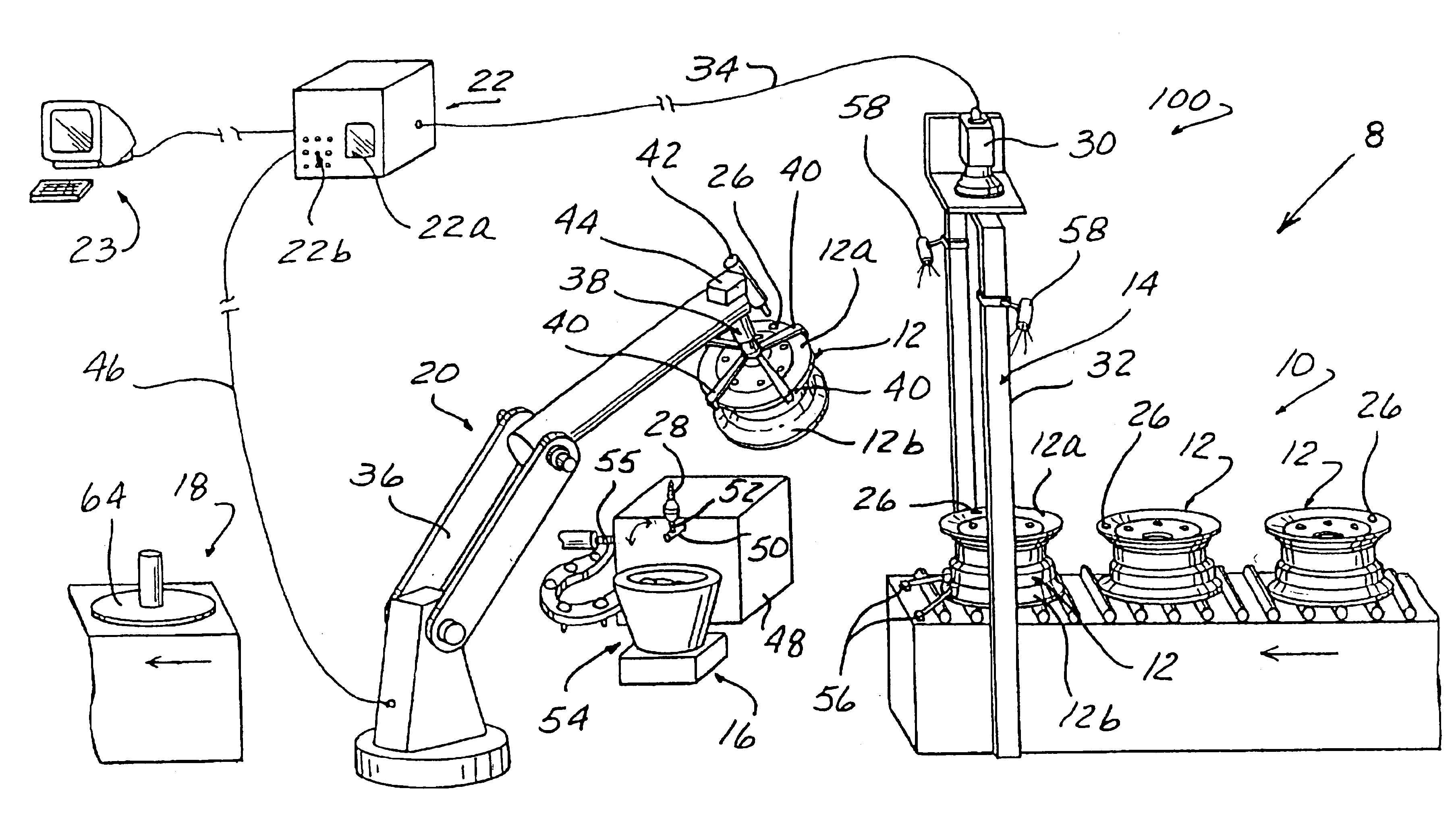
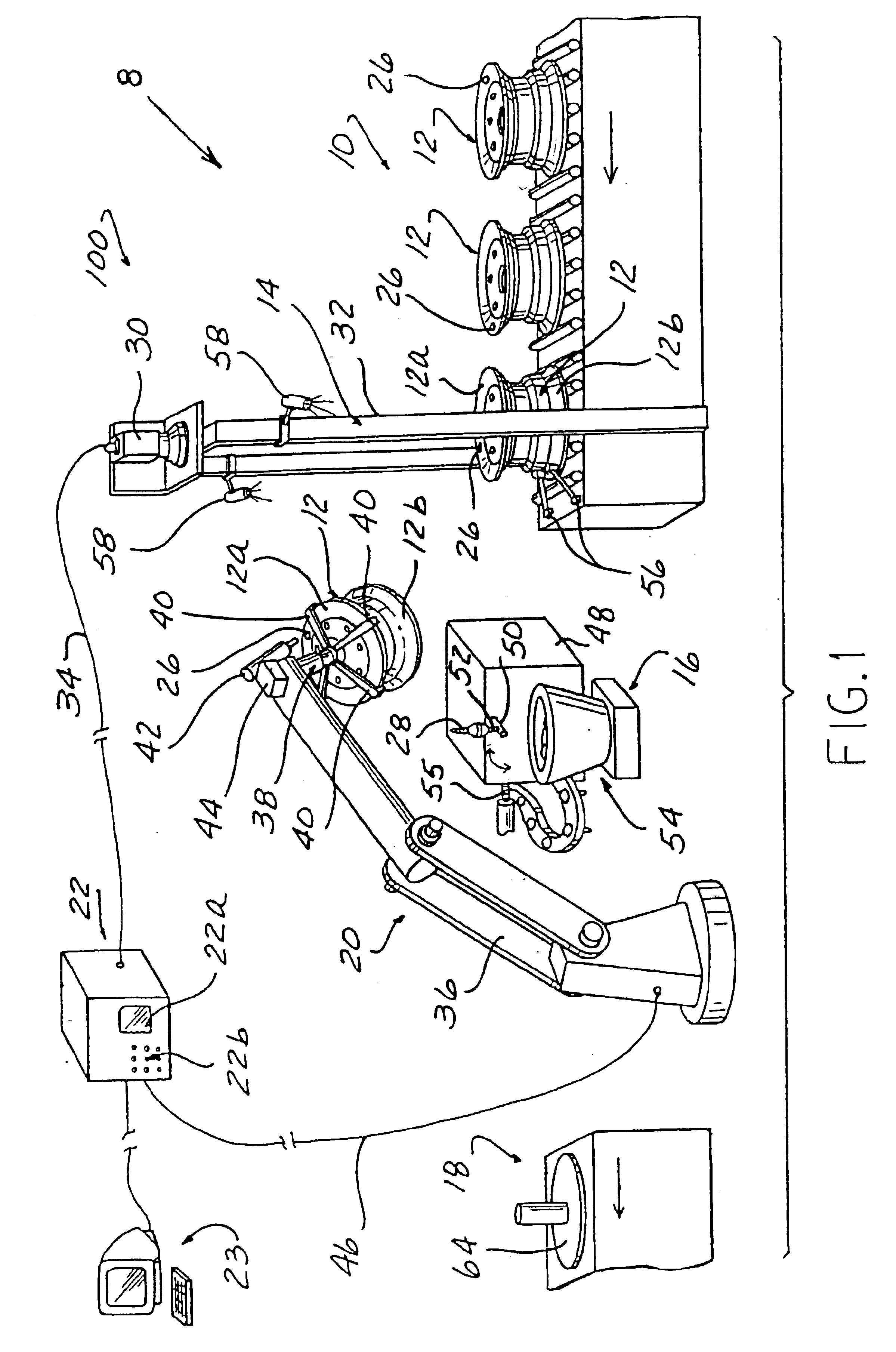
[0026]As seen in FIG. 1, an automated assembly line 8 for mounting valve stems to wheel rims includes an input conveyor 10 for conveying rims 12 in a single-file fashion, a gauging station 14 adjacent the end of the input conveyor, a valve stem mounting station 16 located adjacent the gauging station, an output conveyor 18 for carrying the assembled wheel / stem units away, and a robotic manipulator 20 for transferring the rims from the gauging station to the mounting station and then to the output conveyor.

[0027]Operation of the automated assembly line 8 is monitored and directed by an electronic control system, indicated schematically at 22. The control system 22 includes input / output means such as a display screen 22a and a keypad 22b for allowing a human operator (not shown) to receive information regarding the status of the line and program desired modes of operation. The control system unit 22 can be connected to and / or integrated with other information processing systems so tha...


PUM

PropertyMeasurementUnit
sizeaaaaaaaaaa
physicalaaaaaaaaaa
volumeaaaaaaaaaa

Abstract

An apparatus and method for mounting a valve stem to the rim of an automotive vehicle wheel includes rims being supplied in series by a conveyor to a gauging station where the type and/or size of the rim and the location and alignment of an aperture for receiving the valve stem is determined by a machine vision system. An electronic control system directs a robotic manipulator to grasp either the valve stem or the rim, move the valve stem or the rim to a mounting station, position the valve stem or the rim with respect to the other such that the aperture in the rim is in coaxial alignment with the valve stem, and insert the valve stem through the aperture in the rim. If necessary, a power-actuated nut runner, mounted on the robotic manipulator or adjacent the mounting station, is used to tighten a nut over the valve stem. As an alternative to the machine vision system, the gauging station can use a rotating table which rotates the wheel about a central axis, and an “electric eye” optical sensor directing a beam of infrared light onto the rim. As the rim rotates through the beam, the presence or lack of a reflection of the light beam is used to detect the location of the aperture, and rotation of the table is stopped when the aperture is in alignment with the beam. A probe mounted on the gauging station can be extended to project into the aperture to confirm that the aperture is at the desired position and reposition the rim slightly to provide a precise positioning of the aperture.

Description

CROSS REFERENCE TO RELATED APPLICATION[0001]The present application is a continuation-in-part of Ser. No. 09 / 344,042 filed on Jun. 25, 1999 now U.S. Pat. No. 6,481,083.FIELD OF THE INVENTION[0002]The present invention relates to the assembly of wheels for automotive vehicles, and more specifically to a new apparatus and method for mounting a valve stem on a wheel rim.BACKGROUND OF THE INVENTION[0003]The great majority of wheels produced for automotive vehicles include a metal rim, a tubeless tire mounted on the rim, and a valve stem projecting through an aperture in the rim to communicate with the interior of the tire and permit inflation.[0004]In the past, automobile wheels have been assembled using primarily manual labor. In particular, the mounting of the valve stem to the rim has been accomplished by a hand-held stem inserter tool such as that disclosed in U.S. Pat. No. 3,852,839 and U.S. Pat. No. 4,807,343. Similarly, the mounting of the tire on the rim has involved a worker pl...

Claims


Application Information

Patent Timeline
Patent Type & Authority Patents(United States)
IPC IPC(8): B25J9/16B23P19/04B60C25/00B60C25/18
CPCB23P19/04B25J9/1697B60C25/18B25J9/1664Y10T29/53591Y10T29/49829Y10T29/53039Y10T29/53448Y10T29/53552Y10T29/4978Y10T29/49764Y10T29/49771Y10T29/49778Y10T29/53061Y10T29/49769B60C25/185B60C25/0554
Inventor LAWSON, LAWRENCESACHS, KARL D.
Owner BURKE E PORTER MACHINERY
Why Eureka
Try Eureka