Positionable lift stand

a lift stand and positioning technology, applied in the field of lift stands, can solve the problems of adversely increasing the packaging size, inconvenience for users, and not having the ability to fix the lift stand with a stroke, so as to reduce the number of parts needed to assemble the lift stand, reduce manufacturing processes, and facilitate storage

Active Publication Date: 2018-03-13
WISTRON CORP
View PDF39 Cites 3 Cited by
  • Summary
  • Abstract
  • Description
  • Claims
  • Application Information

AI Technical Summary

Benefits of technology

[0009]Based on the above-described structural configuration, the sliding member of the lift stand of the instant disclosure is actuated by the restoring force of the elastic member, such that the sliding member is movable in an up-and-down fashion relative to the support structure for adjusting the height of the display. When the lift stand is to be packaged, the sliding member is forced to slide to the bottom end of the support structure. Next, the fixing member is used to pass through the first positioning hole and the second positioning hole of the support structure and the sliding member, respectively. Thus, the position of the sliding member becomes fixed and would not back-slide upwardly under the restoring force of the elastic member. Therefore, by utilizing the fixing member and positioning holes formed penetratingly through respective components of the lift stand, the lift stand could be easily kept in occupying least amount of space for packaging or storing purpose. Such attribute is achieved by using fewer parts and requires less manufacturing processes. In doing so, the number of parts necessary to assemble the lift stand can be reduced, with more cost savings and less assembling time.

Problems solved by technology

However, some lift stands are not fitted with stroke fixing capability.
That is, the lift stand is typically left at its maximum reach, which adversely increases the packaging size.
Furthermore, if the lift stand is pre-oriented at its maximum reach, the lift stand may start to yield due to the weight of the display during the assembling process, causing inconvenience for the user.
However, the majority of stroke fixing devices have complex structures.
This fact means extra cost would be spent for molding the parts, along with additional time needed in labor and assembling process.

Method used


Image

  • Positionable lift stand
  • Positionable lift stand
  • Positionable lift stand

Examples


Embodiment Construction

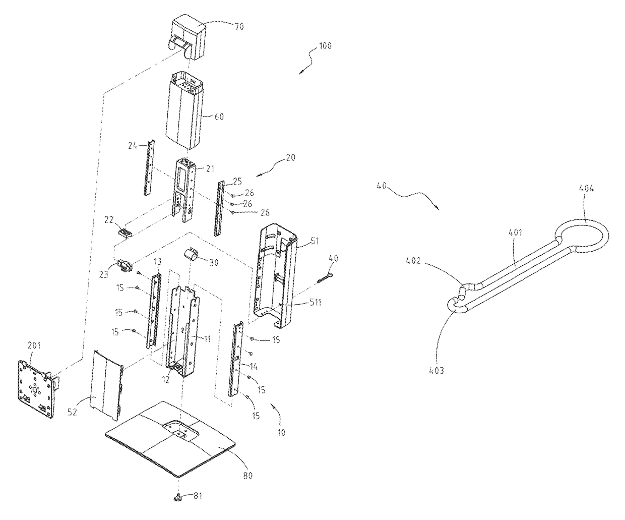
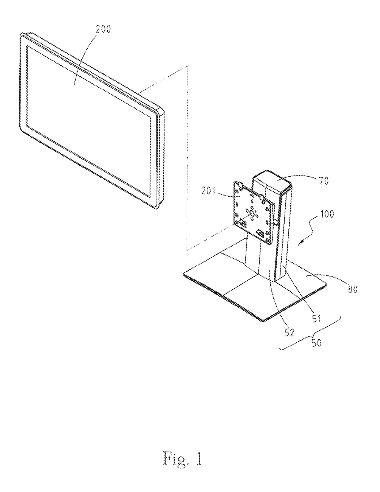
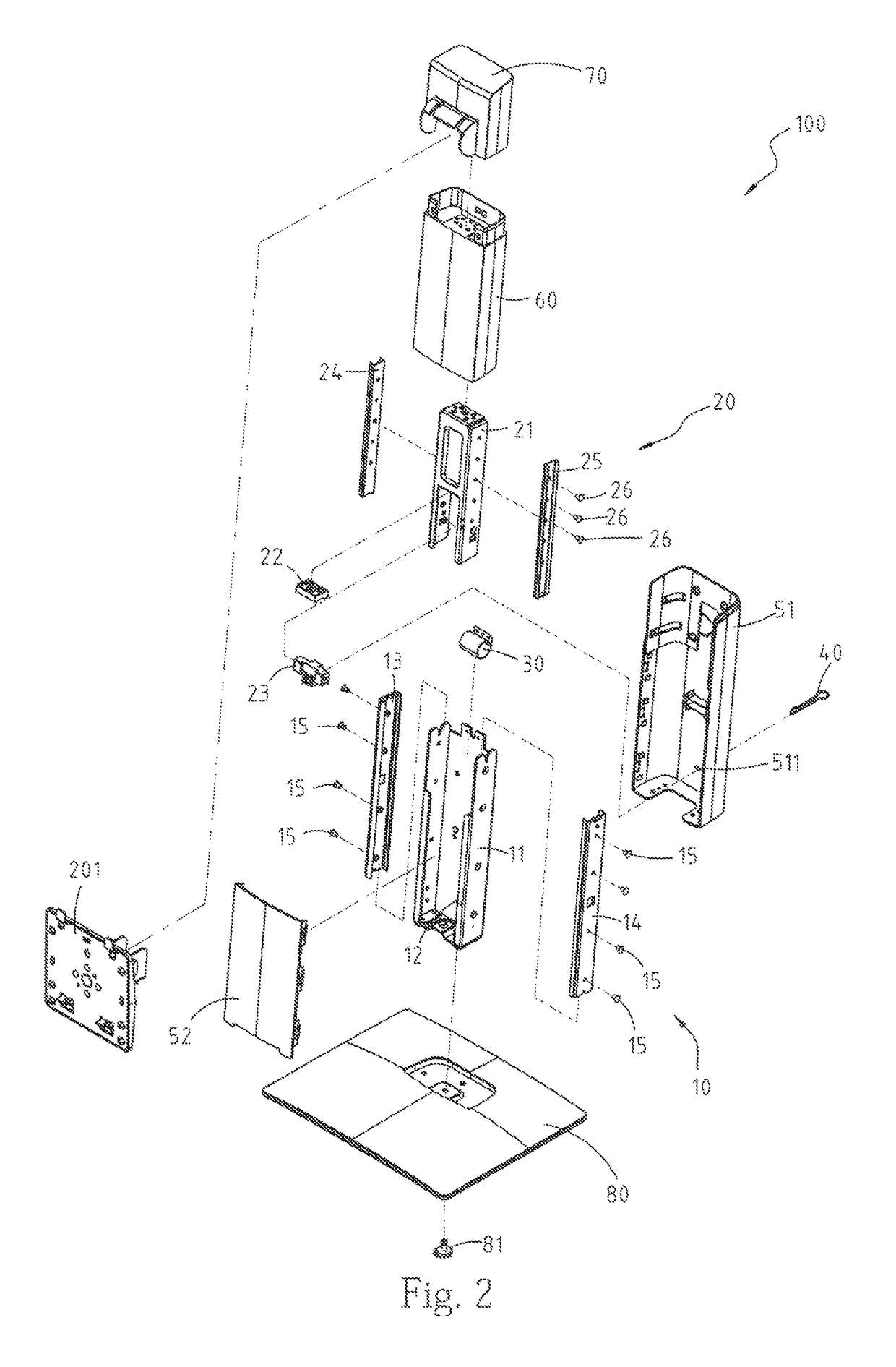
[0022]Please refer to FIGS. 1˜9. FIG. 1 is a schematic view of a lift stand in use for an embodiment of the instant disclosure. FIG. 2 is an exploded view of the lift stand, while FIGS. 3˜4 are cross-sectional views thereof. FIGS. 5 and 6 are perspective views of a support structure and a sliding member, respectively, for the current embodiment. FIG. 7 is a schematic view of assembling the lift stand for the present embodiment, while FIGS. 8 and 9 are respective rear views of the lift stand. The lift stand 100 of the instant disclosure comprises a support structure10, a sliding member 20, an elastic member 30, and a fixing member 40. As shown in FIG. 1, the lift stand 100 is capable of connecting to a display 200, so as to adjust the height of the display 200 by the user. FIGS. 1 and 3 further illustrate the display 200 that includes a mounting member 201, for connecting to the sliding member 20 of the lift stand 100.

[0023]Please refer to FIGS. 2 and 5. The support structure 10 incl...


PUM


Abstract

A positionable lift stand includes a support structure defining a first positioning hole, a sliding member slidably engaged with the support structure and defines a second positioning hole, an elastic member, and a fixing member. The elastic member is connected between the support structure and the sliding member, while provides a restoring force enabling the sliding member to move against the support structure. The fixing member passes through the first positioning hole of the support structure and the second positioning hole of the sliding member. By utilizing the fixing member and various positioning holes associated with the lift stand, the lift stand can be fixedly held to occupy the least amount of space for packaging or storing purpose. Such attribute is achieved by using fewer parts and processing steps, which means fewer parts need to be manufactured, more cost savings, and less assembling time.

Description

CROSS-REFERENCES TO RELATED APPLICATIONS[0001]This non-provisional application claims priority under 35 U.S.C. § 119(a) on Patent Application No. 201420568289.2 filed in China, P.R.C. on 2014 Sep. 29, the entire contents of which are hereby incorporated by reference.BACKGROUND[0002]Technical Field[0003]The instant disclosure relates to a lift stand, in particular, to a positionable lift stand.[0004]Related Art[0005]With the advancement in technology and computerization, along with the popularization of thin-type electronic visual displays, various types of display can be seen in places such as business stores, work locations, or residential complexes. These displays allow the users to control or view what is being displayed. In order to meet various user requirements or adapt to operating environments, displays are often in need of adjustable stands, so that the user can adjust the position or height of the display accordingly.[0006]Several types of support structure for accommodati...

Claims


Application Information

Patent Timeline
Patent Type & Authority Patents(United States)
IPC IPC(8): A47F5/00F16M11/28F16M11/10
CPCF16M11/28F16M11/10F16M2200/048
Inventor CHEN, GUANG-ZHAO
Owner WISTRON CORP
Why Eureka
Try Eureka