
Nasal adapter system for CPAP respiration

a technology of cpap and adapter system, which is applied in the direction of respirator, respiratory mask, etc., can solve the problems of not ideal producing pressure sores on or in the nose or on the face of the child, and the force and torque of the head, so as to minimize the accumulation of co2, facilitate the child's movement, and adapt to the individual size and shape of the head. simple

Active Publication Date: 2018-04-10
DRAGERWERK AG
View PDF15 Cites 0 Cited by
  • Summary
  • Abstract
  • Description
  • Claims
  • Application Information

AI Technical Summary

Benefits of technology

[0019]A basic object of the present invention is to provide a nasal adapter system or a CPAP nasal adapter system, by means of which the pneumatic connection between the breathing tubes (especially the distal breathing tubes) and a prong or a nasal mask can be designed such that optimal adaptation of the entire nasal adapter system to the shape of the head and the size of the head of the patient to be respirated can be achieved. The adapter system must be able to be adapted to the patient's head, especially to the head of a newborn or premature infant, such that the position of the prong or nasal mask relative to its position in relation to the nose will not possibly change due to movements of the child. Forces and torques that may be generated due to movements of the child and of the breathing tubes relative to one another shall not ideally produce pressure sores on or in the nose or on the face of the child. At the same time, good and simple adaptation to the individual size and shape of the head shall be made possible by the CPAP nasal adapter system according to the present invention. In addition, the CPAP nasal adapter system shall make possible the greatest possible freedom of movement for the child. The flow resistance, especially the expiratory flow resistance, shall also be as low as possible. Finally, the smallest dead space possible shall be obtained due to the nasal adapter system according to the present invention, so that only the smallest possible percentage of the air expired during a preceding breathing cycle will be inhaled again during the current breathing cycle in order to thus minimize the accumulation of CO2 in the patient's airways and / or in the dead space of the adapter system.
[0022]To accomplish the above objects, the nasal adapter system according to the present invention must be preferably designed (1) to make possible an angular adjustment of the prongs or nasal mask coupled to (or integrated with) the nasal adapter system relative to the adapter proper, (2) to make it possible to adapt the proximal breathing tubes of the nasal adapter system to the shape and size of the child's head, (3) to offer the greatest possible number of degrees of freedom due to the adapter system in order to limit the freedom of movement of the child to be respirated as little as possible, (4) to keep the dead space of the nasal adapter combined with the prong or the nasal mask as small as possible, and (5) to minimize the flow resistance especially during exhalation.
[0024](2) The breathing tubes (preferably proximal breathing tubes) coupled to the distal end of the adapter are provided with a plastically deformable fiber in order to make it thus possible to adapt the tubes to the shape and the size of the head of the patient, especially a newborn or premature infant. However, the proximal breathing tubes, which are preferably provided between the adapter and the distal breathing tubes, may also be omitted in an alternative embodiment. At least the proximal ends of the breathing tubes may be provided with a plastically deformable fiber in this case.(3) The proximal breathing tubes of the adapter may be coupled rotatably and / or pivotably to the distal breathing tubes, which are directly or indirectly connected with the respirator.(4) The nasal adapter and the articulated connection between the adapter and the nasal mask or prong are designed such that they form the smallest dead space possible in order to minimize the accumulation of CO2 within the adapter system and consequently in the airways of the patient.(5) The breathing gas is routed due to the geometry of the nasal adapter such that a lower flow resistance will develop.
[0035]A projection, which strikes a stop on the adapter housing in an end position, as a result of which excessive rotation of the tube element is prevented, is preferably provided on the tube element.
[0038]The tube element may be held between the proximal openings of the inspiratory channel and of the expiratory channel such as to make it possible to change the angle set between the nasal adapter and the connection nozzle.

Problems solved by technology

Forces and torques that may be generated due to movements of the child and of the breathing tubes relative to one another shall not ideally produce pressure sores on or in the nose or on the face of the child.

Method used


Image

  • Nasal adapter system for CPAP respiration
  • Nasal adapter system for CPAP respiration
  • Nasal adapter system for CPAP respiration

Examples


Embodiment Construction

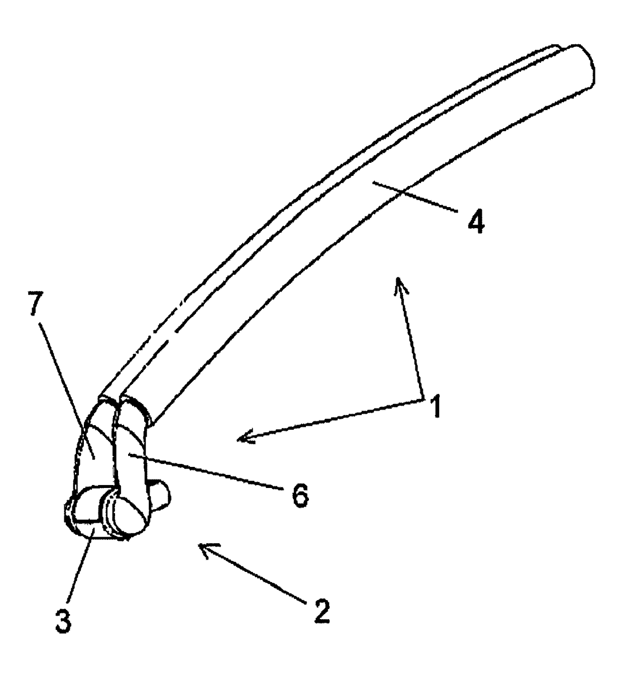
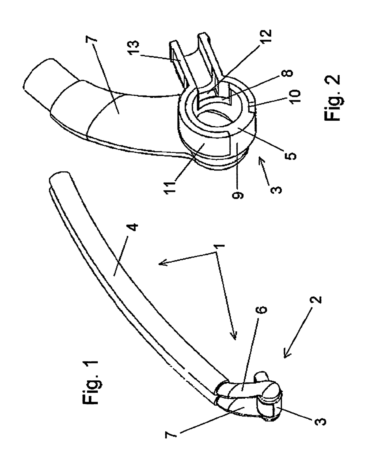
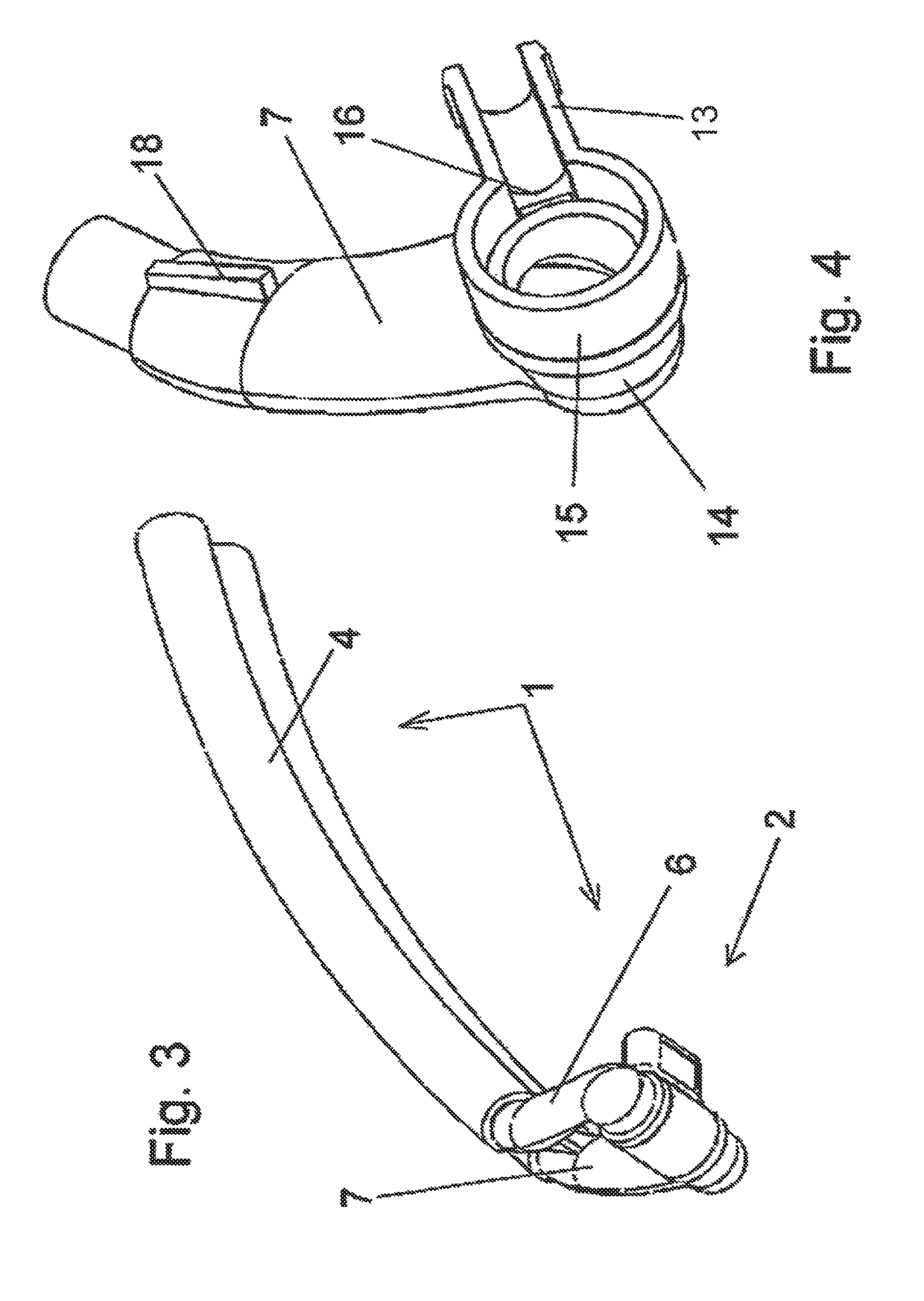
[0067]Referring to the drawings and in particular with reference to FIG. 1, an exemplary embodiment of the CPAP nasal adapter system 1 according to the present invention will be described below. The nasal adapter system 1 comprises essentially the nasal adapter 2 proper, which is provided with a joint 3 at its proximal end and at the distal end of which the proximal breathing tubes 4 of the adapter system are arranged. Not shown are the distal breathing tubes, which are coupled to the distal ends of the proximal breathing tubes 4 and lead to a respirator (not shown) or to other respiration device. As an alternative, the distal breathing tubes may, however, also be connected directly with the distal end of the adapter 2.

[0068]The proximal breathing tubes 4 comprise an inspiratory tube and an expiratory tube, which are arranged next to each other and are connected to one another, as this will be explained below.

[0069]As was described above, the proximal ends of the proximal breathing ...


PUM


Abstract

A nose adapter (2) and system, for use in noninvasive respiratory support, has a proximal end, for coupling to the nose, and a distal end for coupling to a ventilation device. An inspiratory channel (6) and an expiratory channel (7) extend between the proximal and distal end. The distal ends of the channels terminate in a respective connection adapter (30, 31) for connecting ventilation tubes (4). The proximal ends of the inspiratory and the expiratory channels are bent inwards 90° such that the openings of the channels face each other. A cylindrical tube element (34), rotatably held between the openings, has a through-opening in the cylindrical circumferential surface of the tube element. A connection nozzle (13) connects to a prong or a nose mask and is formed on the outer face of the rotatable tube element (34), in alignment with the through-opening, such that the connection nozzle can pivot.

Description

CROSS REFERENCE TO RELATED APPLICATIONS[0001]This application is a United States National Phase Application of International Application PCT / EP2012 / 004983 filed Dec. 3, 2012 and claims the benefit of priority under 35 U.S.C. § 119 of German Patent Application DE 10 2011 120 217.3 filed Dec. 5, 2011, the entire contents of which are incorporated herein by reference.FIELD OF THE INVENTION[0002]The present invention pertains, in general, to a nasal adapter system for use in respiration in the area of intensive care. The present invention pertains, in particular, to a nasal adapter system that is used in CPAP (Continuous Positive Airway Pressure) respiration or NIV-CPAP respiration and is preferably designed to couple a nasal mask or a nasal insert part (hereinafter called “prong”) with the breathing tubes (inspiratory tube, expiratory tube and optional auxiliary tubes) of a respirator or other respiration device.BACKGROUND OF THE INVENTION[0003]There has increasingly been a changeover ...

Claims


Application Information

Patent Timeline
Patent Type & Authority Patents(United States)
IPC IPC(8): A61M16/06A61M16/08A61M16/00
CPCA61M16/065A61M16/0057A61M16/0666A61M16/0875A61M16/0825A61M16/0833A61M16/0816
Inventor KUNZ, RAINERBOTTIGER, SANDRAWAGNER, STEPHANIE
Owner DRAGERWERK AG
Learn More