

Hand-held vacuum cleaner
a vacuum cleaner and hand-held technology, applied in the direction of suction cleaners, suction filters, suction hoses, etc., can solve the problems of increasing the force required to tip over the vacuum cleaner, increasing the difficulty of manoeuvre to the location of the hose, and increasing the force required, so as to reduce the likelihood of collected dirt escaping, reduce the efficiency of the vacuum cleaner, and increase the turbulence within the air flow
Active Publication Date: 2018-04-17
GREY TECHNOLOGY
View PDF57 Cites 23 Cited by
- Summary
- Abstract
- Description
- Claims
- Application Information
AI Technical Summary
Benefits of technology
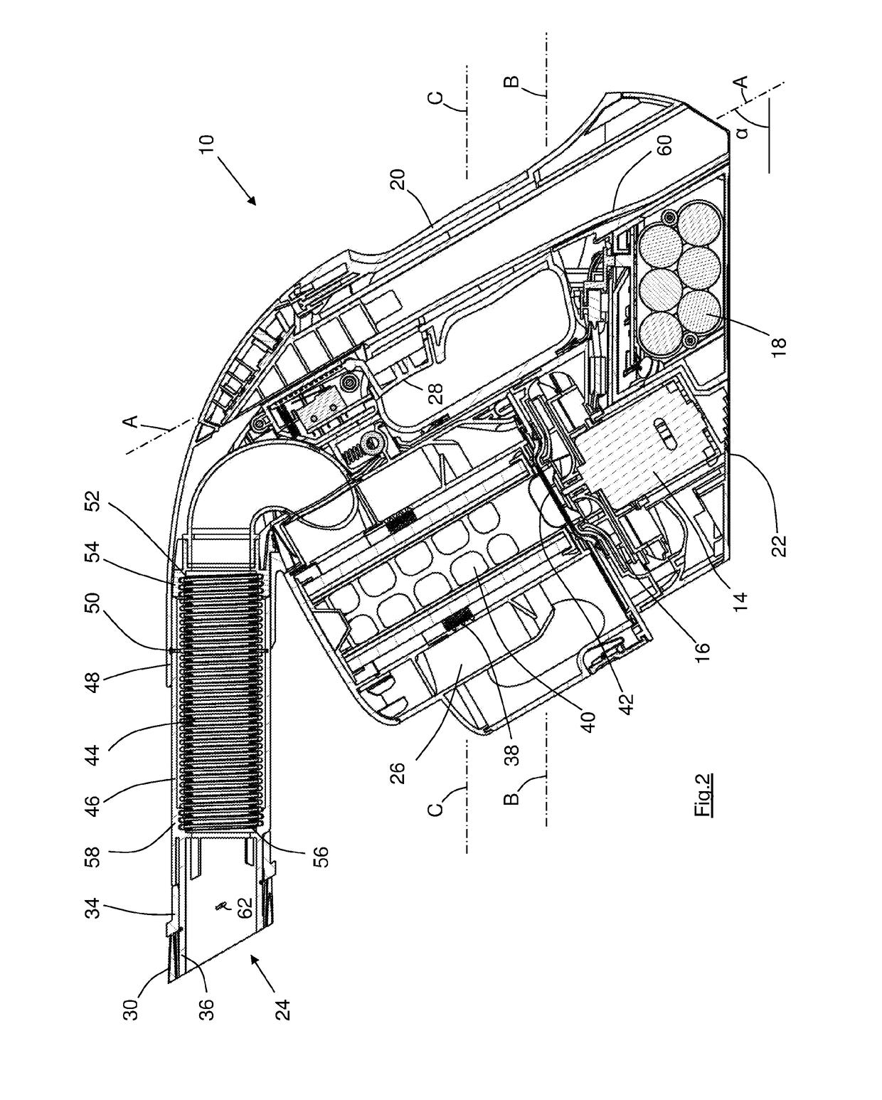
[0024]It will be recognised that the motor and the battery (or more usually the battery pack) are typically the heaviest individual components of the vacuum cleaner, and that locating these components between the base and the collector acts to lower the centre of gravity towards the base. The present inventor has therefore appreciated that lowering the centre of gravity will increase the comfort of use of the vacuum cleaner, and thereby allow it to be used for extended periods of time without undue fatigue of the user.
[0067]The vacuum cleaner according to this tenth aspect can have differently coloured regions, with for example the nozzle, further tube and carrying handle sharing the same colour so as to emphasise the connection between these components. The nozzle, further tube and carrying handle could thereby replicate the appearance of the handle of a cylinder vacuum cleaner, and this is expected to increase the appeal of the vacuum cleaner and perhaps also to alert customers to the intended purpose of the vacuum cleaner in supplementing a cylinder (or upright) vacuum cleaner.
Problems solved by technology
Once again, however, the hose is difficult to manoeuvre to the location of use, and the resilience of the hose increases the force which must be provided in order to reach less accessible locations.
The force required often exceeds that required to tip over the vacuum cleaner, and it is known for an upright vacuum cleaner to fall over during periods of use of the extended hose.
It may not be possible to reach more remote locations (such as the ceiling above a flight of stairs for example) without also lifting the body of the vacuum cleaner off the floor.
An upright vacuum cleaner is totally unsuited to above-floor cleaning and a cylinder vacuum cleaner is not ideally suited for such an operation.
Also, the known hand-held cleaners are not well suited to cleaning the large surface areas involved.
There is therefore presently no vacuum cleaner which is designed for, and which is therefore well-suited to, above-floor cleaning, for example the routine cleaning of large areas such as walls and ceilings.
The force with which the coil spring seeks to unwind can be significant, and if the user attempts to resist the unwinding then parts of the hose can collapse, with the result that less air can flow therealong.
Allowing the coil spring to unwind as it is stretched it is not always desirable.
When the hose is extended and the coil spring unwinds, the user will likely have to re-orient the cleaning tool.
The addition of a rotatable joint represents additional manufacturing cost.
Also, a rotatable joint is relatively bulky compared to the remainder of the extendable hose and the joint can become stiff over time.
This necessarily results in the rotatable joint restricting the air flow path, and increasing the likelihood of the hose becoming blocked adjacent to the rotatable joint.
The reduced air flow is therefore suffered during the major proportion of the vacuum cleaner's usage during which the hose is connected to the suction head and the rotatable joint is redundant.
Method used
View moreImage
Smart ImageViewing Examples

Examples
first embodiment
[0077]FIG. 8 shows a side view of an extendable flexible hose;
[0078]FIG. 9 shows a cross-sectional view of the hose of FIG. 8;
[0079]FIG. 10 shows a perspective view of the hose of FIG. 8;
second embodiment
[0080]FIG. 11 shows a cross-sectional view of extendable flexible hose;
[0081]FIG. 12 shows a perspective view of the hose of FIG. 11;
[0082]FIG. 13 shows a cut-away perspective view of a modified collector of the vacuum cleaner according to the invention;
[0083]FIG. 14 shows a view of the baffle of the collector of FIG. 13; and
[0084]FIG. 15 shows a side view of an extension brush for use with the vacuum cleaner.
Login to View More PUM
 Abstract
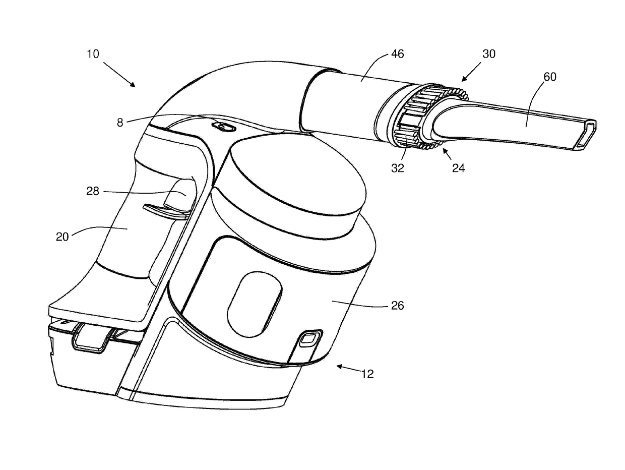
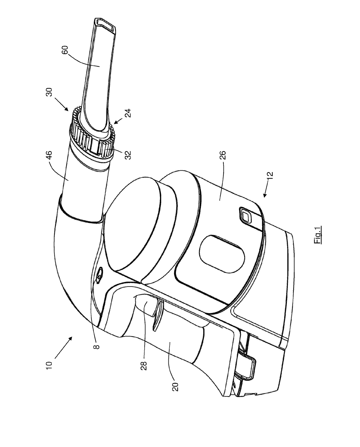
This invention relates to a hand-held vacuum cleaner (10). The vacuum cleaner is expected to have particular utility for cleaning locations which are difficult to reach with a conventional vacuum cleaner. The vacuum cleaner (10) has a body (12) with a substantially planar base (22) upon which the vacuum cleaner can rest when not in use, the body having a carrying handle (20), a motor (14) and an impeller (16) located within the body, the vacuum cleaner also having a collector (26, 126) and a battery pack (18), the battery pack providing at least a part of the base (22). The motor and the battery pack are located between the base and the collector so as to lower the center of gravity and make the vacuum cleaner more comfortable for use, especially over long periods. Ideally, the center of gravity is close to the carrying handle, and between the carrying handle and the nozzle so that the vacuum cleaner is slightly “nose heavy”.
Description
FIELD OF THE INVENTION[0001]This invention relates to a hand-held vacuum cleaner and to an extendable hose.[0002]The vacuum cleaner is expected to have particular utility for cleaning locations which are difficult to reach with a conventional vacuum cleaner suction head, such as would normally be cleaned with the vacuum cleaner tools, including stairs, upholstery, the upper or ceiling corners of rooms where cobwebs and debris can accumulate, and also light fittings, for example. The extendable hose may be used with the hand-held vacuum cleaner, but is not limited to such use as explained below.[0003]In the following description, directional and orientational terms such as “below”, “bottom” etc. are to be understood in relation to the hand-held vacuum cleaner in its normal orientation of use as defined below (and as shown in FIGS. 1-7).BACKGROUND TO THE INVENTION[0004]The owners or occupiers of many domestic and commercial premises utilise a vacuum cleaner to clean the floors and oth...
Claims
Login to View More Application Information
Patent Timeline
 Patent Type & AuthorityPatents(United States)
IPC IPC(8): A47L5/24A47L9/24A47L9/06A47L9/19A47L9/28
CPCA47L5/24A47L9/0606A47L9/2831A47L9/24A47L9/244A47L9/19
InventorGREY, NICHOLAS GERALDVAGGES, CHRISTOPHER
OwnerGREY TECHNOLOGY