Disk image acquiring device and disk sorting device

a technology of which is applied in the field of disk image acquisition and disk image sorting device, can solve the problems of increasing the cost and increasing the size of the whole device, and reducing the discrimination accuracy

Active Publication Date: 2018-04-17
ASAHI SEIKO CO LTD
View PDF20 Cites 0 Cited by
  • Summary
  • Abstract
  • Description
  • Claims
  • Application Information

AI Technical Summary

Benefits of technology

[0016]The present disclosure has been made in view of the above-described conventional technologies, and an feature thereof is to provide a disk image acquiring device which can acquire taken images of whole patterns formed on disk surfaces of a plurality of kinds of disks having different diameters easily and securely.
[0017]Another feature of the present disclosure is to provide a disk image acquiring device which can expand a diameter range of a disk which can be discriminated.
[0018]Still another feature of the present disclosure is to provide a disk image acquiring device which can be made small in size even if a diameter range of a disk which can be discriminated is expanded.

Problems solved by technology

This is because discrimination accuracy lowers if a portion of an image of the pattern is not taken.
In other words, there is such a problem that a diameter range of a coin which can be discriminated is small.
On the other hand, when the image-taking region is expanded so as to conform to the large-diameter coin, there is such a problem that the image sensor or an illumination device becomes large in size, which results in cost increase and increase in size of the whole device.
Though use of a lens having a wide field angle does not require increase in size of the image sensor, increase in size of the illumination device is unavoidable.
Further, since the center position varies according to the diameter of the coin, there is also such a problem that because a general method as detecting an outer periphery of a coin to obtain the center position of the coin is applied when the center position of the coin constituting a reference for image discrimination is obtained, a processing time required for image discrimination becomes long.
Therefore, there is a problem similar to that in the coin discriminating device described in Japanese Unexamined Patent Application Publication No. 2001-344631.
In the coin image identifying device described in Japanese Unexamined Patent Application Publication No. 2007-241701, since the image-taking timing is calculated from the image-taking position of the coin and the coin transportation velocity, an error occurs easily regarding the image-taking time, so that deviation occurs regarding the center position of the coin to the image-taking region.
Therefore, since it is necessary to set the image-taking region large in anticipation of a size corresponding to the error, there is such a problem that the image sensor or the illumination device becomes large in size, which results in cost increase and increase in size of the whole device.
Further, since deviation of the center position of the coin occurs, there is also such a problem that because such a general method as detecting an outer periphery of a coin to obtain the center position is applied like the cases described in Japanese Unexamined Patent Application Publication Nos. 2001-344631 and 2002-358551 when the center position of the coin constituting a reference for image discrimination is obtained, a processing time required for image discrimination becomes long.
In the work image-identifying device described in Japanese Patent No. 3115505, since the plurality of coin position detectors corresponding to diameters of coins are required, there is such a problem as increase in cost.
Further, since positions and optical axes of the plurality of coin position detectors must be adjusted, there is such a problem that adjusting work becomes complicated.

Method used


Image

  • Disk image acquiring device and disk sorting device
  • Disk image acquiring device and disk sorting device
  • Disk image acquiring device and disk sorting device

Examples


Embodiment Construction

[0053]Embodiments of the present disclosure will be described below with reference to the accompanying drawings.

[0054](Configuration)

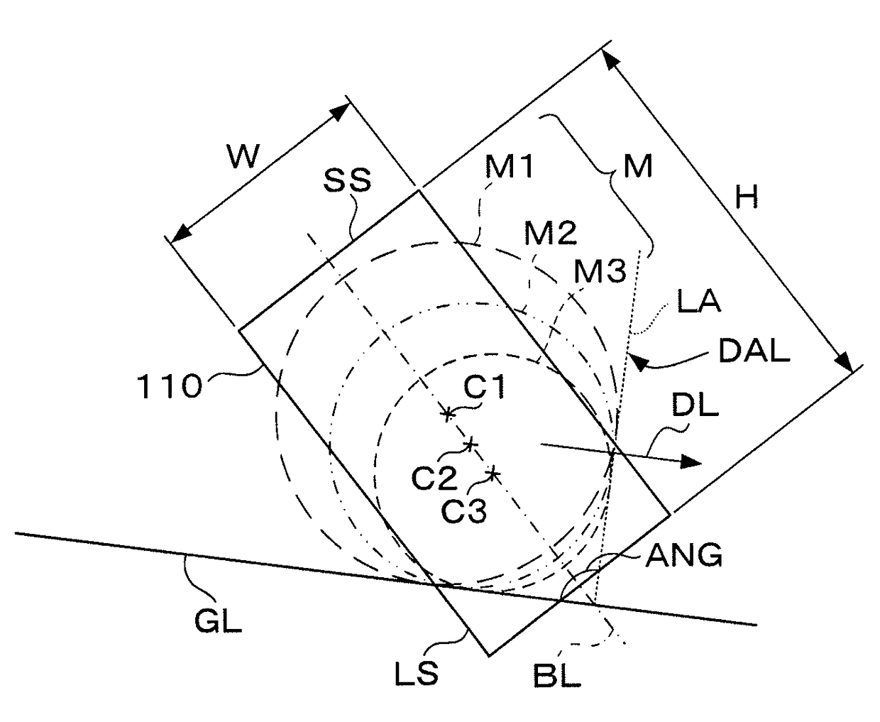
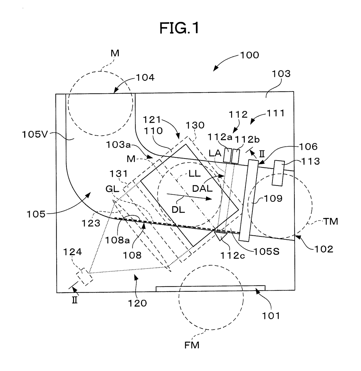
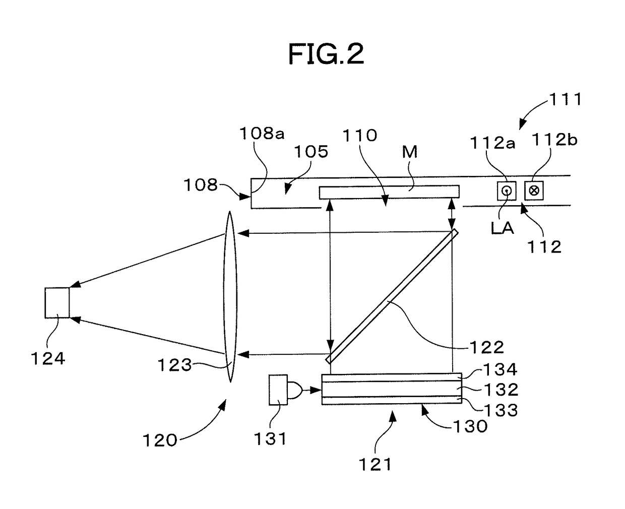
[0055]As one example of a disk sorting device according to the present disclosure, a medal sorting device 100 shown in FIGS. 1 to 4 will be described. The medal sorting device 100 is incorporated into a game machine or the like to be used, and has a function of making discrimination about authenticity of a medal which has been slotted to sort a false medal FM to a medal return slot 101 and guiding a true medal TM to a medal reception port 102. The medal sorting device 100 includes a main body 103, the medal slot 104, a medal passage 105, a sorting gate 106, a two-dimensional imager (imaging device) 120, a timing sensor to take images 111, a medal counting sensor 113, a controller 140, a ROM (Read Only Memory) 142, a RAM (Random Access Memory) 143, a user interface 151, a status display 152, a registration switch 53, and a security volume 154.

[0056]The ...


PUM


Abstract

Disk image acquiring device includes a guide for guiding a peripheral surface of a disk moving in a predetermined direction along a predetermined guide line, an imaging window defining an image-taking region on the one surface of the disk, a timing sensor to take images having a detection axis traversing a moving direction of the disk and outputting a timing signal as arrival of the disk at a predetermined position on the imaging window when the peripheral surface of the disk has been detected on the detection axis, and an imager which takes an image of the one surface of the disk via the imaging window based upon the timing signal, wherein a bisector of an angle between the guide line and the detection axis is utilized as a base line, and the imaging window is extended along the base line.

Description

BACKGROUND OF THE DISCLOSURE[0001]1. Field of the Invention[0002]The present disclosure relates to a disk image acquiring device, and in particular relates to a disk image acquiring device which takes an image of a pattern formed on a surface or a back surface of a disk to acquire a taken image. More specifically, the present disclosure relates to a disk image acquiring device which can also acquire images regarding a plurality of kinds of disks having different diameters easily and securely.[0003]Also, the present disclosure relates to a disk sorting device, and in particular relates to a disk sorting device which takes an image of a pattern formed on a surface or a back surface of a disk to acquire a taken image, compares the taken image with a reference image to discriminate authenticity of the disk, and sorts the disk based upon the discrimination result. More specifically, the present disclosure relates to a disk sorting device which can acquire images regarding a plurality of ...

Claims


Application Information

Patent Timeline
Patent Type & Authority Patents(United States)
IPC IPC(8): H04N7/18G07D5/00
CPCG07D5/005
Inventor SUZUKI, DAISHI
Owner ASAHI SEIKO CO LTD
Why Eureka
Try Eureka