
Lock Mechanism of Electric Connection Box

a technology of locking mechanism and electric connection box, which is applied in the directions of locking device, electric apparatus casing/cabinet/drawer, transportation and packaging, etc., can solve the problem of weakening the lock retention, and achieve the effect of convenient and secure operation

Active Publication Date: 2008-10-23
YAZAKI CORP
View PDF8 Cites 0 Cited by
  • Summary
  • Abstract
  • Description
  • Claims
  • Application Information

AI Technical Summary

Benefits of technology

[0011]Having been conducted in view of solving the above-described problems in the related art, it is an object of the present invention to provide a lock mechanism which allows not only an improvement of the operability for locking and unlocking but also an enhancement of lock retention in a locked state in an electric connection box.

Problems solved by technology

On the other hand, if the flexural rigidity of the lock arm is reduced so as to eliminate the need for applying a large force for locking and unlocking operations, the lock retention will be weakened.

Method used


Image

  • Lock Mechanism of Electric Connection Box
  • Lock Mechanism of Electric Connection Box
  • Lock Mechanism of Electric Connection Box

Examples


Embodiment Construction

[0050]Hereinafter, an embodiment of the present invention will be described by referring to drawings. In the following drawings, the same or similar parts are denoted by the same or similar reference numerals.

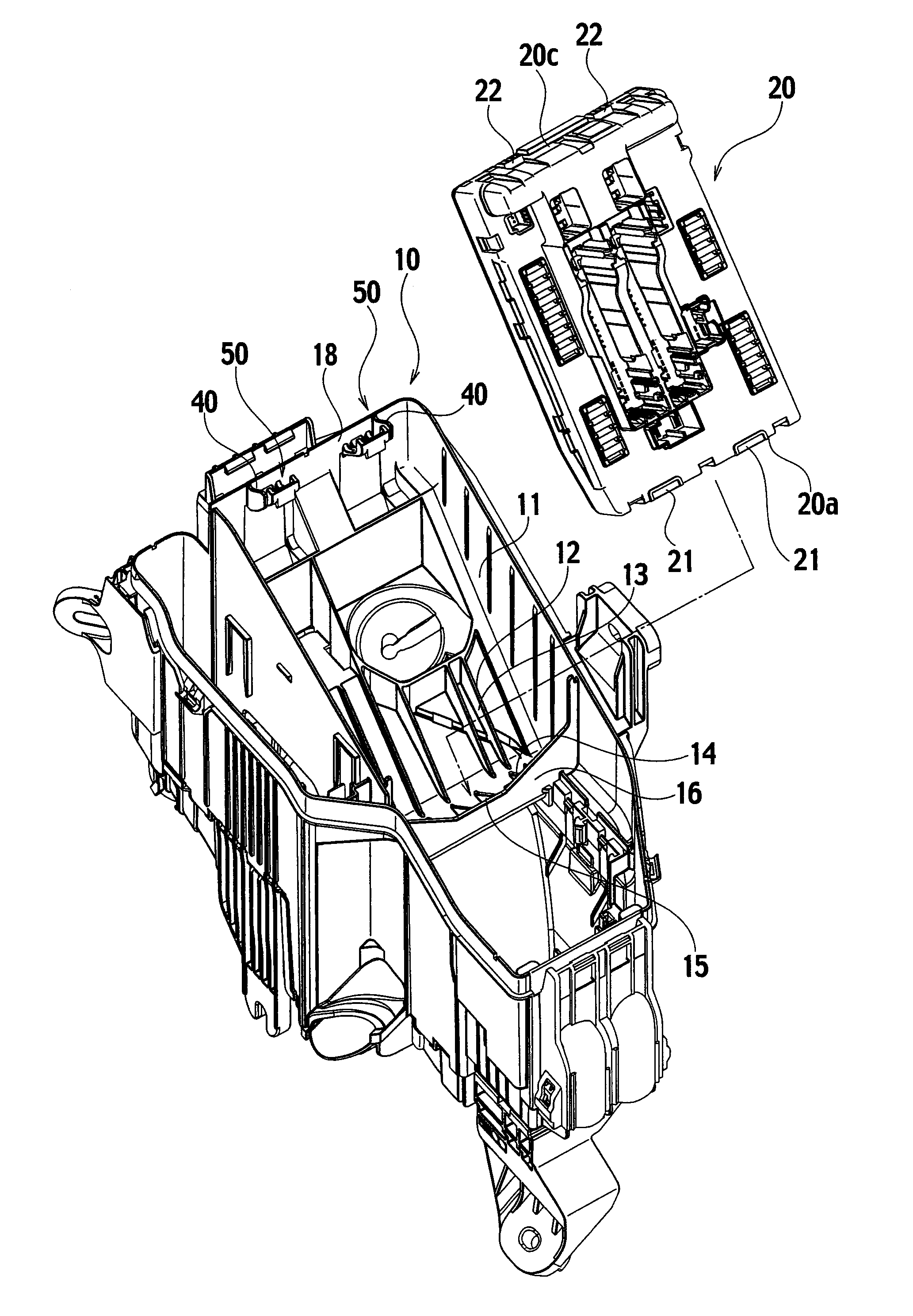
[0051]FIG. 4 is an upper perspective view of an electric connection box employing a lock mechanism according to an embodiment of the present invention, and FIG. 5 is a perspective view of the electric connection box from an angle different from that in FIG. 4. FIG. 6 is a plan view of the electric connection box in a state of being assembled. FIG. 7 is a cross-sectional view taking along the line VII-VII in FIG. 6. FIG. 8 is a drawing of FIG. 7 before a part is housed. FIGS. 9, 10, and 11 are a plan view, an upper perspective view, and a bottom perspective view, respectively, of a lock unit on a box body. FIG. 12 is an upper perspective view of the lock unit from an angle different from that in FIG. 10. FIGS. 13, 14, and 15 are cross-sectional views taken along the line XIII-XI...


PUM


Abstract

A lock mechanism includes: a lock arm provided in a cantilever manner on an inner wall of a part compartment of a box body of an electric connection box; and a lock projection provided to the lock arm on its surface facing a part housed in the part compartment. The lock arm can be divided in a longitudinal direction into: a base end region fixed to the inner wall; upper end region located in the free end which interferes with the part and receives a pressing force for unlocking operation; and a middle region located within a predetermined distance range between the base and upper end region. The flexural rigidity of the base and upper end region is set larger than that of the middle region by providing ribs on the base and upper end region and providing no ribs on the middle region.

Description

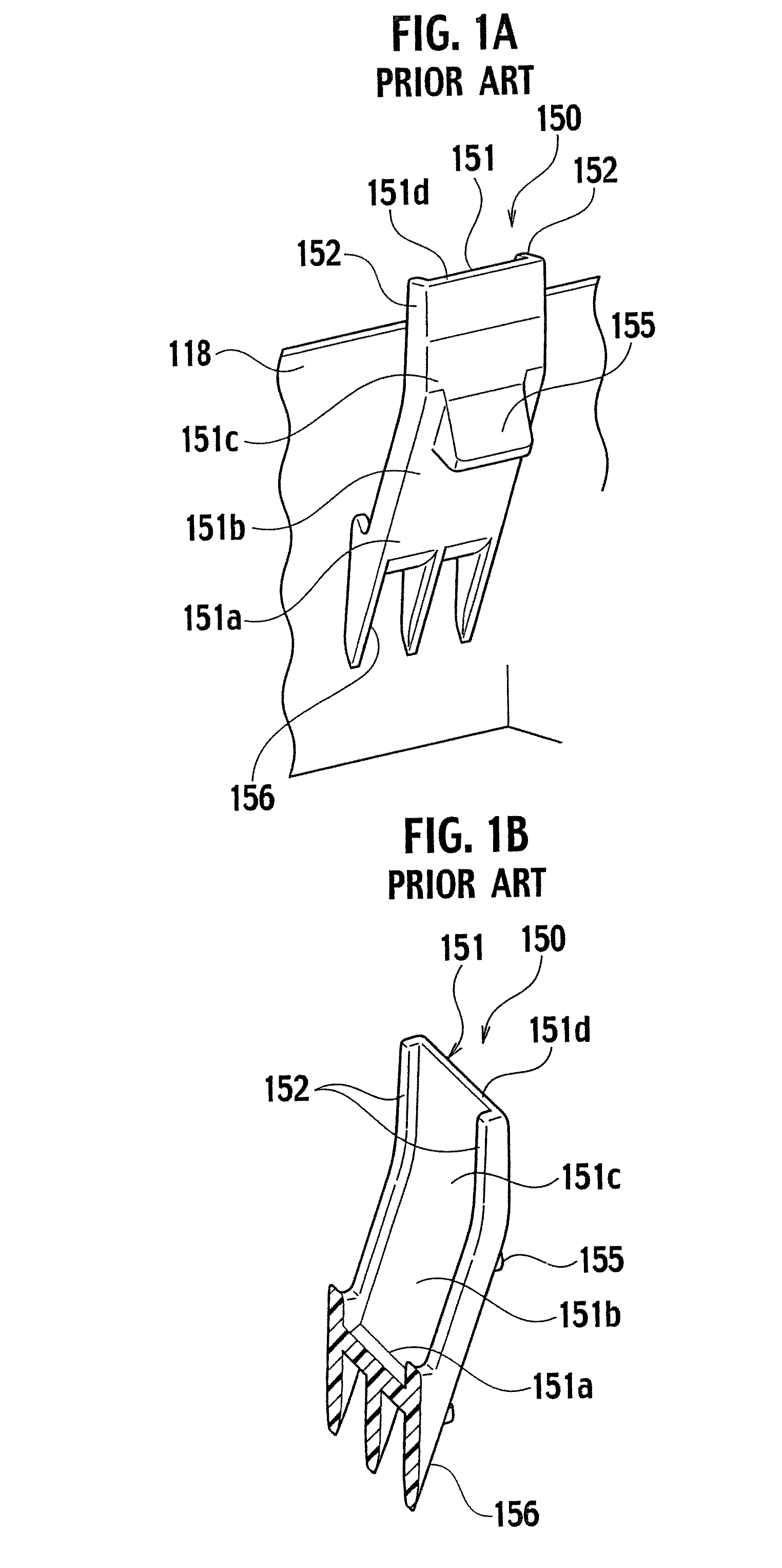
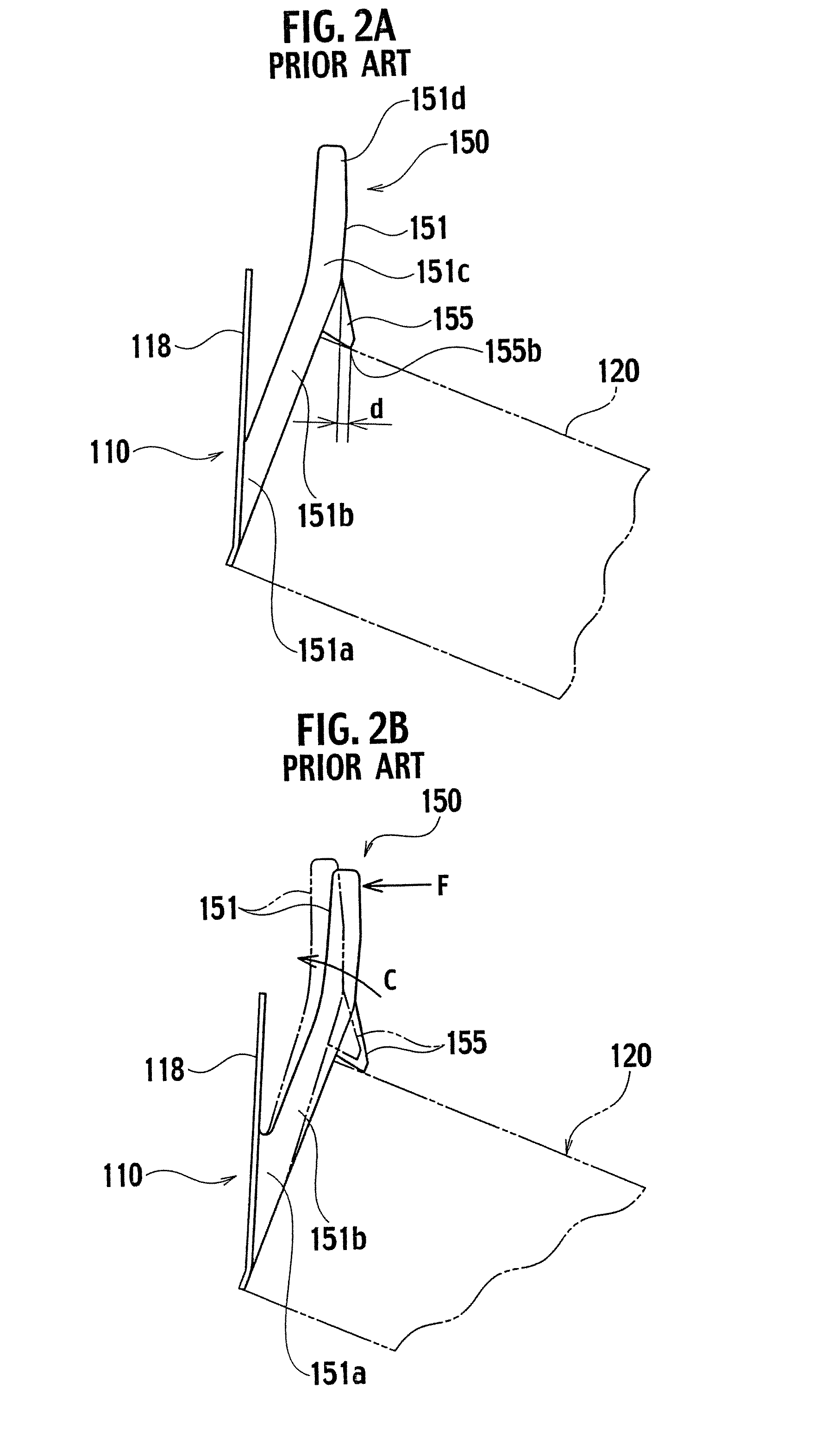
BACKGROUND OF THE INVENTION[0001]1. Field of the Invention[0002]The present invention relates to a lock mechanism of an electric connection box which is mounted in an automobile and the like.[0003]2. Description of the Related Art[0004]An electric connection box for housing fuses, relays and other wire harness components is mounted in a vehicle. In the case where a body of such an electric connection box houses therein a separate part such as a fuse box, a lock unit configured to fix the separate part to the box body is provided therebetween as described in Japanese Unexamined Patent Publication No. 2004-312844 and Japanese Unexamined Patent Publication No. 2005-86865.[0005]As an example of such a lock unit, a lock mechanism 150 shown in FIGS. 1A, 1B, 2A, and 2B includes a flexible lock arm 151 provided on an inner wall 118 of a box body 110, and is configured to fix a part 120, which is a counterpart component, to the box body 110 with a lock projection 155 on the flexible lock arm...

Claims


Application Information

Patent Timeline
Patent Type & Authority Applications(United States)
IPC IPC(8): B65D55/02
CPCH05K5/0221H05K7/026Y10T70/554
Inventor NAKAYAMA, MAKOTOKANAMARU, MASAHIRO
Owner YAZAKI CORP
Learn More