
Association of a portable sensor device in a building management system

a technology of building management system and sensor device, applied in the field of building management system, can solve the problems of limited energy storage and manual action by users

Active Publication Date: 2018-04-24
SCHNEIDER ELECTRIC BUILDINGS AMERICAS INC
View PDF29 Cites 15 Cited by
  • Summary
  • Abstract
  • Description
  • Claims
  • Application Information

AI Technical Summary

Benefits of technology

[0009]A further object of the invention is to provide a method and a system for associating a portable sensor device with a control device which conserves power of the portable sensor device.
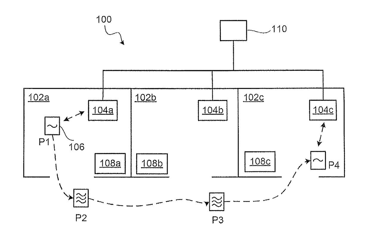
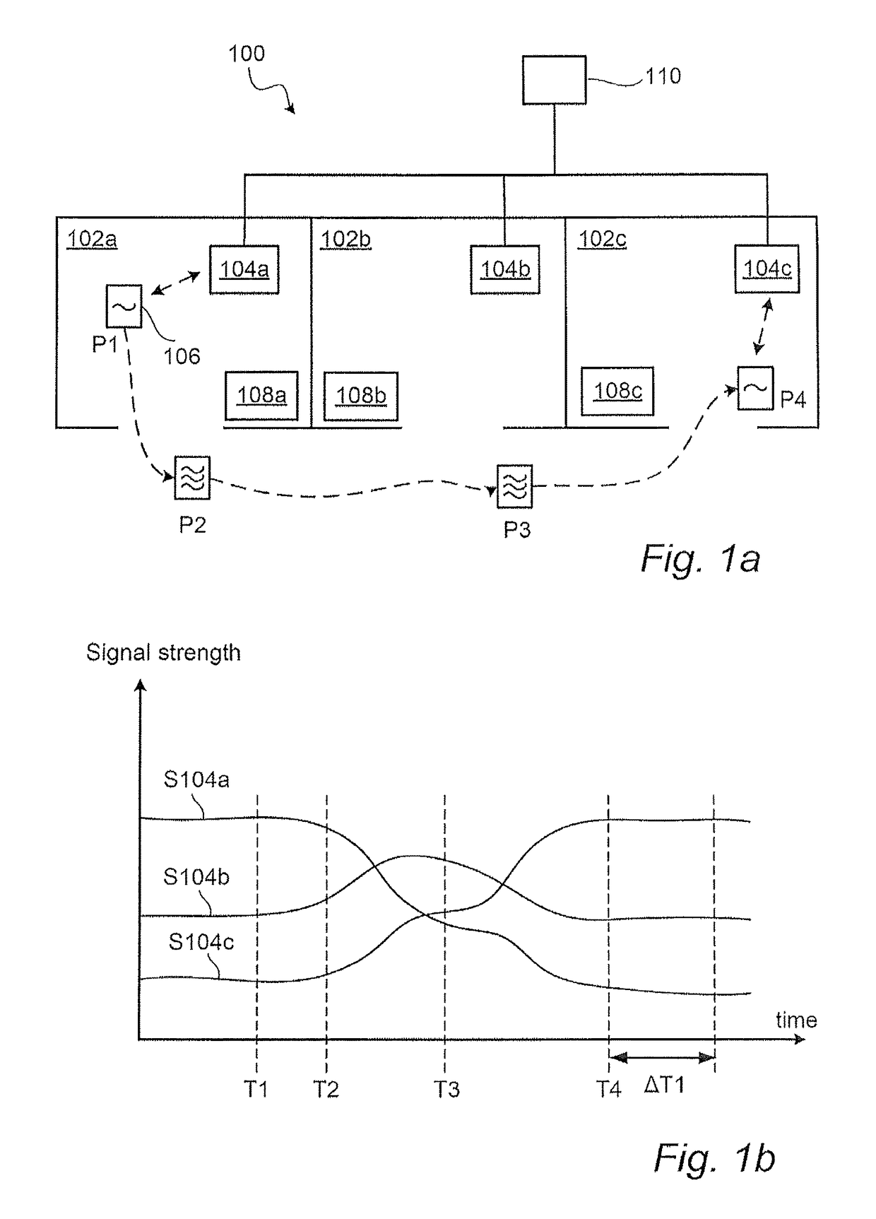
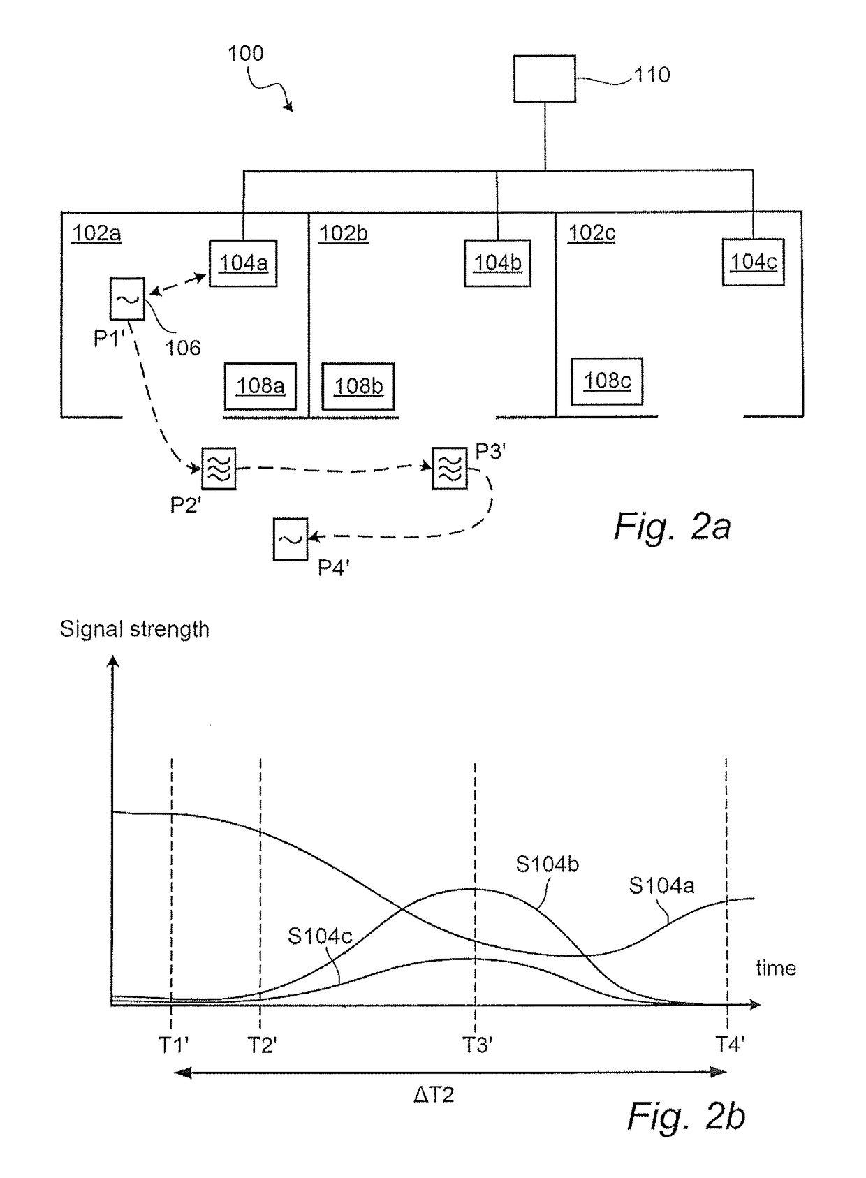
[0012]As the portable sensor device is moved (for example by a user moving the portable sensor device to bring it to another room) movement is detected and the portable sensor device starts to communicate with the control devices at a shorter time interval. In this way, the portable sensor device communicates more often such that the control devices may note that the portable sensor device is moving and such that the movement may be followed.
[0013]The movement may be followed by the control devices receiving the signal strength of the signals emitted by the portable sensor device. It is determined that the movement is stopped when the received signal strengths at the control devices is essentially constant during a predefined time window. If it is determined that the movement has stopped, it is assumed that the user probably has reached his / her final destination and the portable sensor device is then associated with the closest (in geographical sense) control device at the destination defined by the control device having the highest received signal strength. In this way, the portable sensor device is automatically associated with a control device as it is brought to another room and hence no manual operations are needed.
[0014]When the portable sensor device has been associated with a control device it returns to the first mode where it communicates with its associated control device at long time intervals. In this way, the time period the portable sensor device is in an energy consuming mode is made as short as possible.

Problems solved by technology

A general problem with portable sensor devices is that their energy storage is limited since they typically are self-powered or driven by batteries.
A drawback with this approach is that the user manually has to perform an action when he / she enters a new room in order to, for example, set a desired temperature value or to indicate that he / she has entered the room.

Method used


Image

  • Association of a portable sensor device in a building management system
  • Association of a portable sensor device in a building management system
  • Association of a portable sensor device in a building management system

Examples


Embodiment Construction

[0033]The present invention will now be described more fully hereinafter with reference to the accompanying drawings, in which currently preferred embodiments of the invention are shown. This invention may, however, be embodied in many different forms and should not be construed as limited to the embodiments set forth herein; rather, these embodiments are provided for thoroughness and completeness, and fully convey the scope of the invention to the skilled person. The systems and devices disclosed herein will be described during operation.

[0034]FIG. 1a schematically illustrates a building management system 100 being installed in three rooms 102a-c of a building. The building management system 100 comprises a plurality of stationary control devices 104a-c, a portable sensor device 106, and a processing unit 110. The illustrated building management system 100 also comprises stationary sensor devices 108a-c.

[0035]The stationary control devices 104a-c are connected in a wired or wirele...


PUM


Abstract

There is provided a building management system and a method for associating a portable sensor device with a stationary control device in such a system. Upon detection of a movement of the portable sensor device, the portable sensor device starts to transmit signals more frequently to the stationary control devices. It is determined that the movement of the portable sensor device has stopped if the signal strength of the transmitted signals received at the stationary control devices is essentially constant during a time window. In response to such a determination, the portable sensor device is associated with the stationary control device having the highest received signal strength and the portable sensor device returns to an energy-saving mode.

Description

CROSS-REFERENCE TO RELATED APPLICATION[0001]This application is the U.S. national phase of PCT Application No. PCT / US2013 / 037148 filed on Apr. 18, 2013, which claims priority to EP Patent Application No. 12164768.9 filed on Apr. 19, 2012, the disclosures of which are incorporated in their entirety by reference herein.TECHNICAL FIELD[0002]The present invention relates to the field of building management systems. In particular it relates to association of a portable sensor device with a control device in such a system.BACKGROUND[0003]Building management systems may for example be used to supervise and control the indoor climate of a building. Such systems may comprise several control devices which are connected in a network. The control devices may receive measurement data from sensors. Further, a user may input reference values (i.e., set point values) to the control devices, for example in the form of a desired temperature.[0004]Such systems may also comprise portable sensor devices...

Claims


Application Information

Patent Timeline
Patent Type & Authority Patents(United States)
IPC IPC(8): G05B15/02F24F11/00H04W4/00G05D23/19H04W4/80
CPCG05B15/02G05D23/1932H04W4/80F24F11/30F24F2221/12Y02D70/22F24F11/46G05B2219/2642F24F2110/00Y02D30/70F24F2120/00F24F11/63F24F11/56
Inventor BRISSMAN, JAN
Owner SCHNEIDER ELECTRIC BUILDINGS AMERICAS INC
Learn More