System, method, and medium for determining a failure of a network element

a network element and failure technology, applied in the field of cable networks, can solve problems such as negative effects on elements, failures in network elements that serve a large number of accounts,

Active Publication Date: 2018-05-01
CSC HLDG
View PDF3 Cites 12 Cited by
  • Summary
  • Abstract
  • Description
  • Claims
  • Application Information

AI Technical Summary

Problems solved by technology

Failures in network elements that serve a large number of accounts are typically detected whe

Method used


Image

  • System, method, and medium for determining a failure of a network element
  • System, method, and medium for determining a failure of a network element
  • System, method, and medium for determining a failure of a network element

Examples


Embodiment Construction

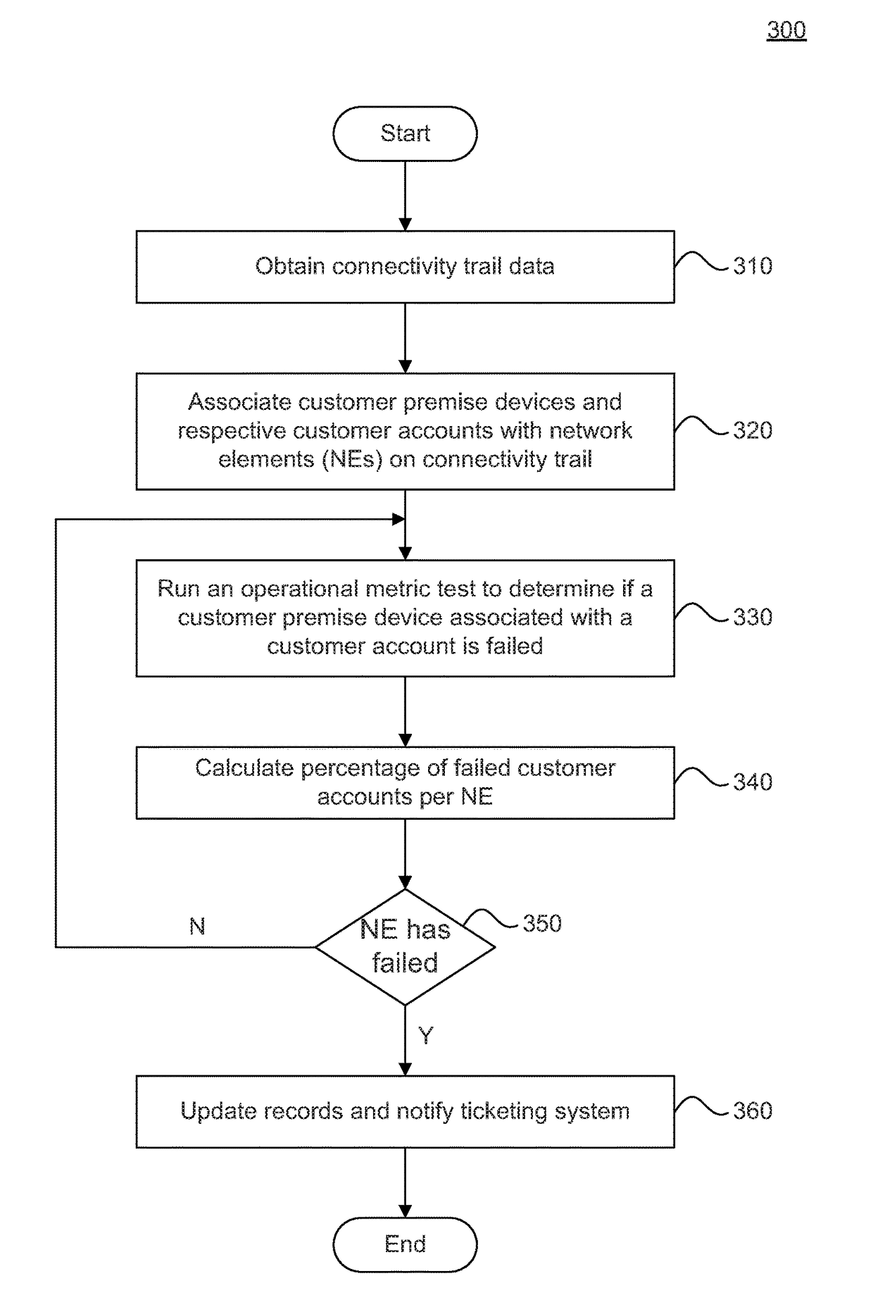
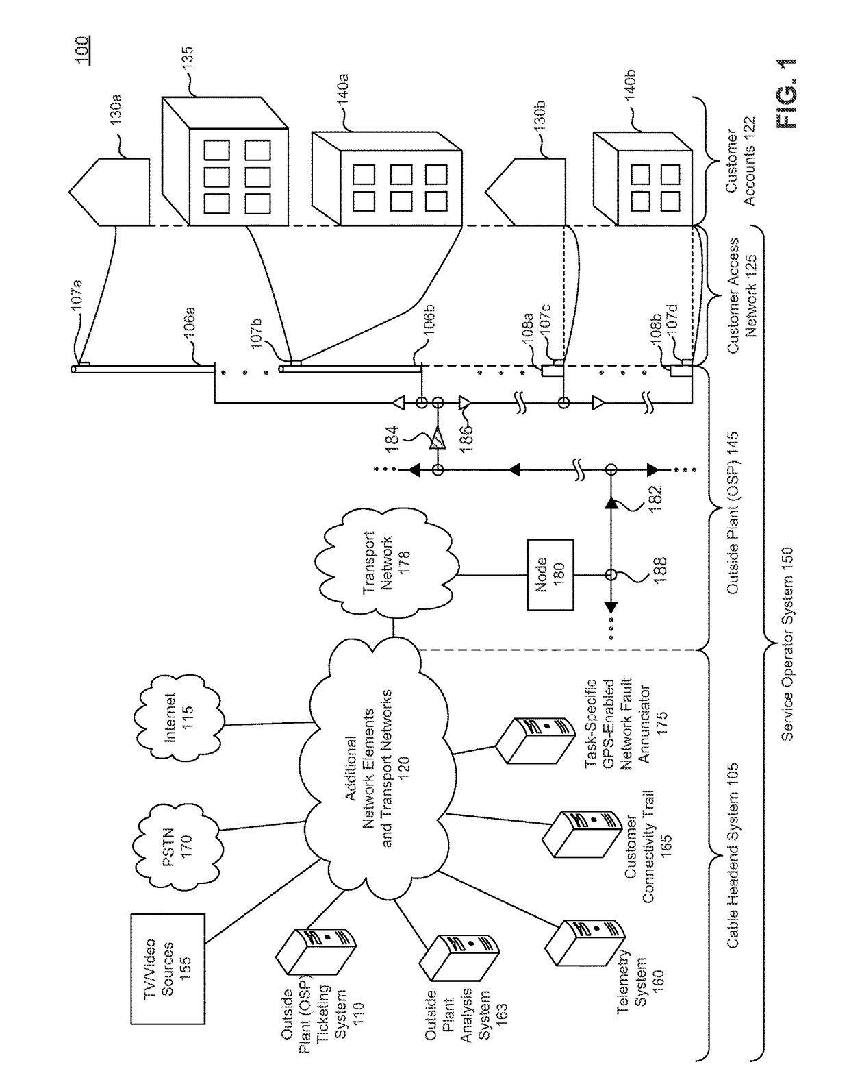
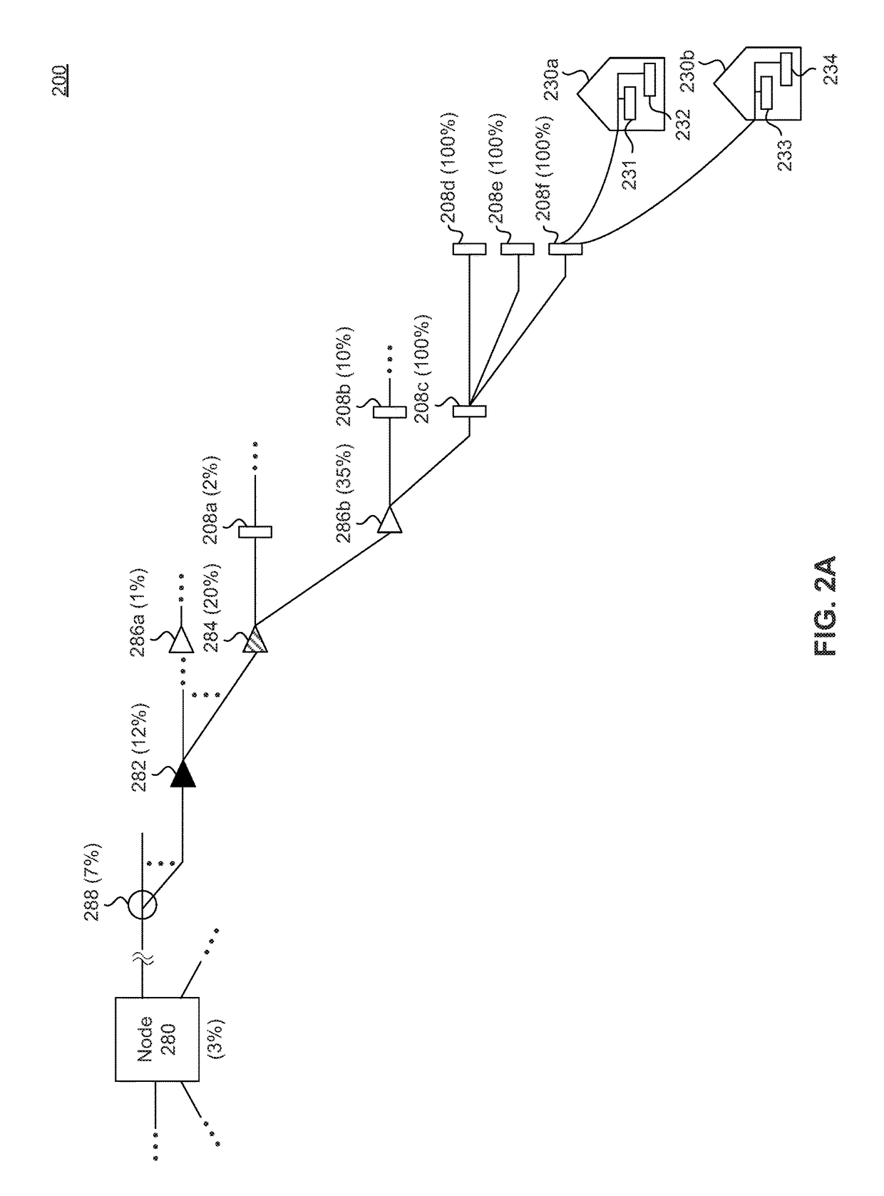
[0009]In conventional cable networks, cable headends are coupled to transport networks and nodes, where nodes are network elements (NEs) that serve a geographic region of about 500 customer accounts. A node typically supports a connectivity trail of about 100 downstream NEs that are coupled to customer premise devices associated with a customer account. Current cable network monitoring node analytics detect node problems when 20% or about 100 of the customer accounts experience service problems. The lack of visibility in the connectivity trail of NEs is problematic, and results in a service provider reactively addressing issues (e.g., after a customer reports a trouble).

[0010]Embodiments detect issues in an outside plant utilizing a connectivity trail of NEs that indicates how NEs are connected within a geographic region that may be served by a cable headend. Embodiments provide visibility into the performance of NEs, and the connectivity trail from a customer premise device associa...


PUM


Abstract

Embodiments detect issues in an outside plant utilizing a connectivity trail that indicates network elements (NEs) starting at the headend and ending at a distribution tap that serves one or more customer premise devices associated to a customer account. Embodiments determine a failed NE that serves the highest number of customers for which a trouble is reported to a ticketing system. Embodiments avoid reporting downstream child NEs that may be performing poorly due to the upstream failed parent NE. Embodiments associate the one or more customer premise devices, and a customer account with respective NEs of the connectivity trail, perform operational metric tests to determine whether a customer premise device associated with a customer account has failed, determine when an NE of the connectivity trail has failed. Embodiments also include rebooting the failed NE and/or notifying a ticketing system accordingly.

Description

BACKGROUNDField[0001]Embodiments generally relate to cable networks and include detecting and managing problems in an outside plant of a cable system.Background Art[0002]Cable systems detect and manage failures in cable networks. Failures in network elements that serve a large number of accounts are typically detected when a significant portion of the accounts served by the network element are negatively affected.BRIEF DESCRIPTION OF THE DRAWINGS / FIGURES[0003]FIG. 1 illustrates an example system according to an embodiment;[0004]FIG. 2A illustrates an example connectivity trail according to an embodiment;[0005]FIG. 2B illustrates an example connectivity trail in tabular form according to an embodiment;[0006]FIG. 3 illustrates a flow for determining outside plant issues according to an embodiment;[0007]FIG. 4 illustrates a flow for determining a failed customer premise device according to an embodiment; and[0008]FIG. 5 illustrates an example computer system which can be used to implem...

Claims


Application Information

Patent Timeline
IPC IPC(8): H04L12/24
CPCH04L41/0631H04L41/507H04L43/0847H04L43/16H04L41/0661
Inventor CRUICKSHANK, III, ROBERTCIOFFI, CHRISBRADY, THOMASHOSSEINZADEH, MAZIARQIAN, JIYUANSHEIKHOLESLAMI, GHOLAMHOSEIN
Owner CSC HLDG
Why Eureka
Try Eureka