
Dome stormwater chamber

a stormwater chamber and dome technology, applied in the field of stormwater management, can solve the problems of system dead load, live load, system failure,

Inactive Publication Date: 2018-05-29
ADVANCED DRAINAGE SYST
View PDF21 Cites 4 Cited by
  • Summary
  • Abstract
  • Description
  • Claims
  • Application Information

AI Technical Summary

Benefits of technology

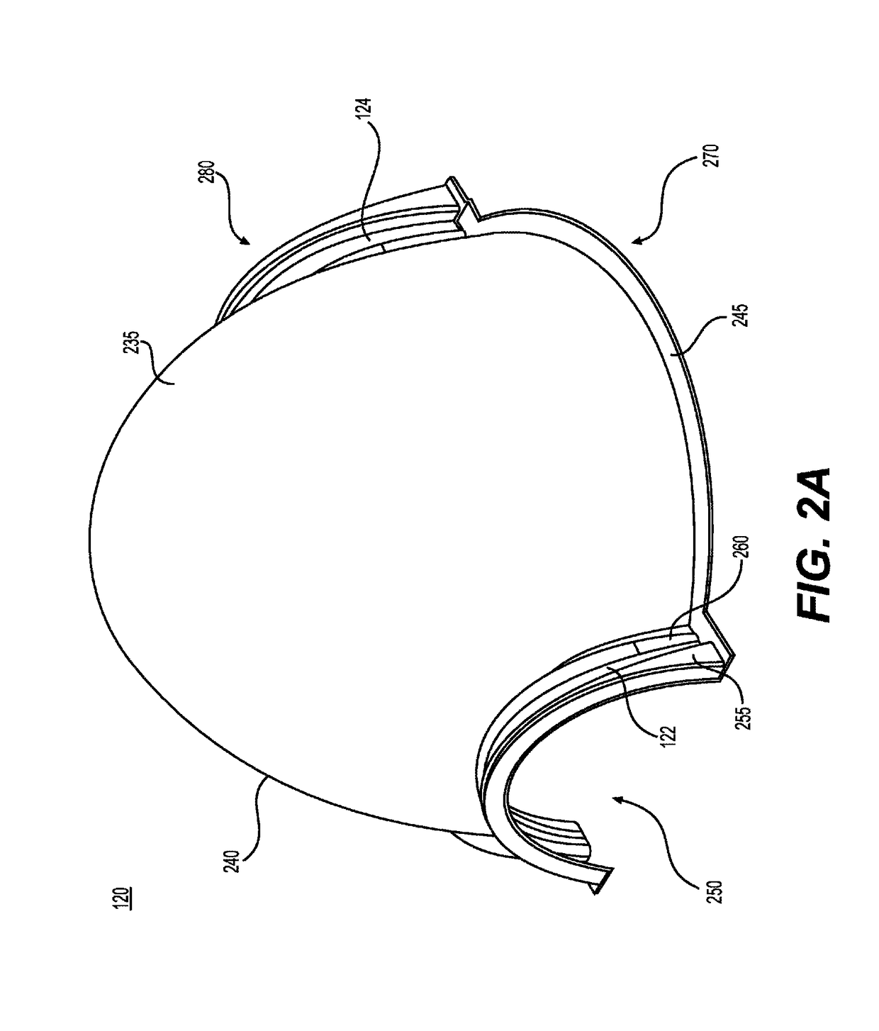
The patent text describes a new design for a chamber used in a stormwater management system. The chamber has a unique shape with a continuous curvature from the apex of the chamber to the base and from the first to second openings. Additionally, the chamber has first and second coupling structures positioned around the openings, and the base of the chamber is curved outward from the coupling structures. The technical effects of this design include better performance and efficiency in managing and controlling the movement of rainwater in the system.

Problems solved by technology

However, stormwater solutions that use cellular crates, boxes, and columns have drawbacks.
Once installed underground, these systems are subjected to dead loads (from the soil above them) and live loads (from passing vehicular and pedestrian traffic).
The dead and live loads create tensional stress and fatigue on the boxes and crates.
These internal supports reduce the amount of void space capable of storing stormwater.
The cellular column systems, while able to carry vertical loads, lack lateral support.
These systems may be subject to stress and fatigue from soil loads on the sides of the columns.
However, existing stormwater chambers occupy a large land area for the volume of stormwater storage they provide.

Method used


Image

  • Dome stormwater chamber
  • Dome stormwater chamber
  • Dome stormwater chamber

Examples


Embodiment Construction

[0022]Reference will now be made in detail to the exemplary embodiments of the present disclosure described above and illustrated in the accompanying drawings.

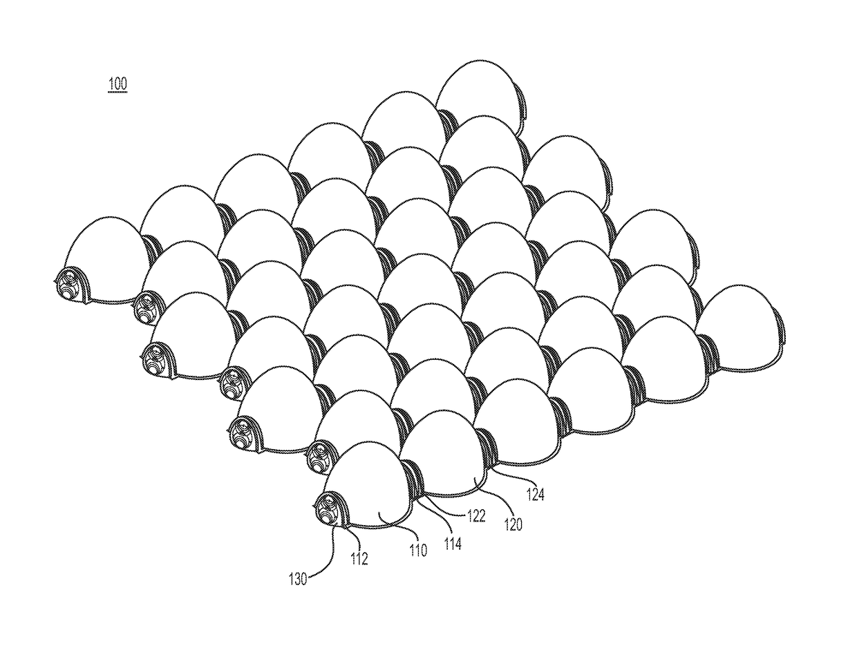
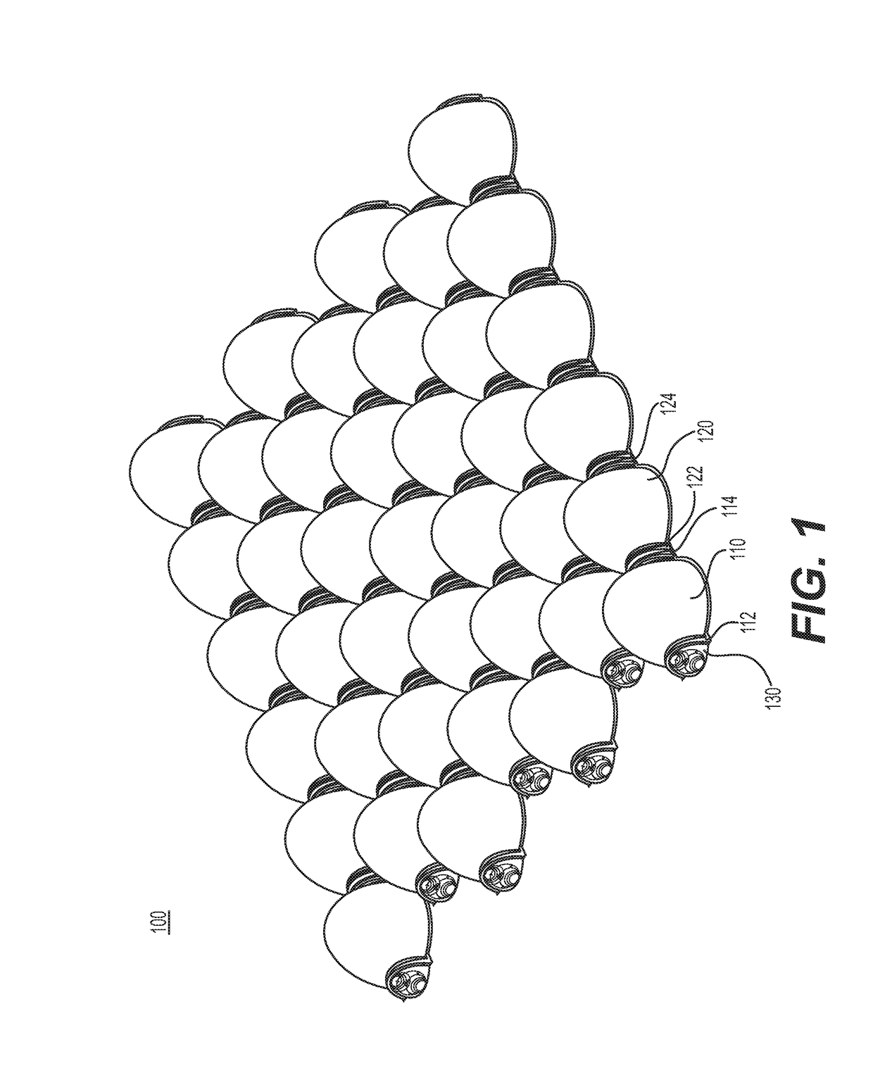
[0023]FIG. 1 illustrates a perspective view of an exemplary stormwater chamber array 100. Stormwater chamber array 100 may include multiple individual stormwater chambers 110, 120 arranged and configured to collect, store, and drain a fluid. Stormwater chamber array 100 may be disposed underground. For example, stormwater chamber array 100 may be installed under a road, sidewalk, field, lot, or other ground surface. Stormwater chamber array 100 may be buried underground and surrounded by a fill material such as soil, sand, stone, gravel, or other appropriate material. Stormwater chamber array 100 may be placed on a geotextile covered surface. In one embodiment, stormwater chamber array 100 may be buried with a depth of foundation stone of approximately 12 inches. Stormwater chamber array 100 may be covered in a geotextile and ...


PUM


Abstract

This disclosure relates generally to stormwater management and, more particularly, to a stormwater chamber with a continuous curvature. The stormwater chamber may comprise a chamber body with a chamber wall, an apex, a base, and a first and second opening. The chamber wall may include a continuous curvature from the apex of the chamber body to the first and second openings and a continuous curvature from the apex of the chamber body to the base.

Description

FIELD OF THE DISCLOSURE[0001]The present disclosure relates generally to stormwater management and particularly to chambers for retaining and detaining water beneath the surface of the earth.BACKGROUND OF THE DISCLOSURE[0002]Generally speaking, stormwater management systems are used to accommodate stormwater underground. Depending on the application, stormwater management systems may include pipes, stormwater chambers, and cellular crates, boxes, or columns. After a large rainfall event, stormwater may need to be collected, detained underground in a void space, and eventually dispersed. The stormwater may be dispersed through the process of infiltration, where the water is temporarily stored and then gradually dissipated through the surrounding earth. Alternatively, the stormwater may be dispersed through the process of attenuation, where the water is temporarily stored and then controllably flowed to a discharge point. Modular crates, boxes, and columns with cells are used for both...

Claims


Application Information

Patent Timeline
Patent Type & Authority Patents(United States)
IPC IPC(8): E03F1/00E01F5/00E02B11/00
CPCE03F1/003E02B11/00E01F5/00
Inventor VITARELLI, RONALD R.KUEHN, MICHAELKURDZIEL, JOHNMAILHOT, DAVID
Owner ADVANCED DRAINAGE SYST
Learn More