Eureka AIR delivers breakthrough ideas for toughest innovation challenges, trusted by R&D personnel around the world.

Static hinge disabler

a technology of disabler and disabler, which is applied in the direction of pin hinges, door/window fittings, constructions, etc., can solve the problems of preventing undesirable door operation, prone to failure of moving components, and inability to use door locks until, so as to prevent undesirable door operation, and save lives

Inactive Publication Date: 2018-06-05
WASAWEGAN ENTERPRISES LLC
View PDF11 Cites 8 Cited by
  • Summary
  • Abstract
  • Description
  • Claims
  • Application Information

AI Technical Summary

Benefits of technology

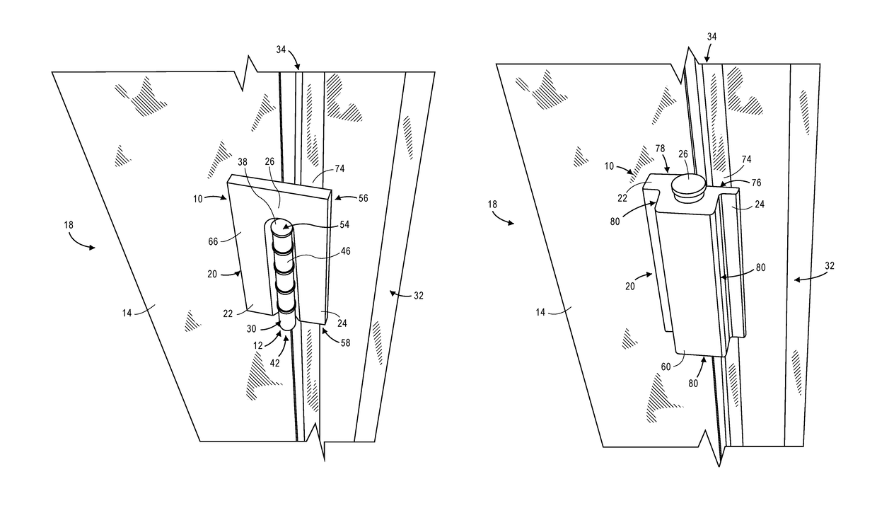
[0005]Embodiments of the invention solve the above-mentioned problems by providing a static hinge disabler. The static hinge disabler offers many advantageous over prior art door locks. First, the static hinge disabler is resistant to damage imparted on the door by being in a protected location away from an engaging portion of the door, i.e., a side of the door on which the doorknob is located. The static nature of the static hinge disabler also means there are no weak components that are prone to failure. Second, the static hinge disabler precludes any picking or disengagement from outside the door by moving the locking mechanism to a position in which it cannot be accessed by a malfeasant outside the door. Third, when emplaced over a top hinge of a door, the static hinge disabler is out of the reach of children to prevent undesirable operation of the door. Fourth, the static hinge disabler need not be permanently installed on the door such that it can be used on any of numerous different doors. Finally, the static hinge disabler is quick and simple to operate. A person need only slide the static hinge disabler over a door hinge to prevent that door from opening, which can save lives in a dangerous situation. The static hinge disabler includes no moving or operational components that can fail.
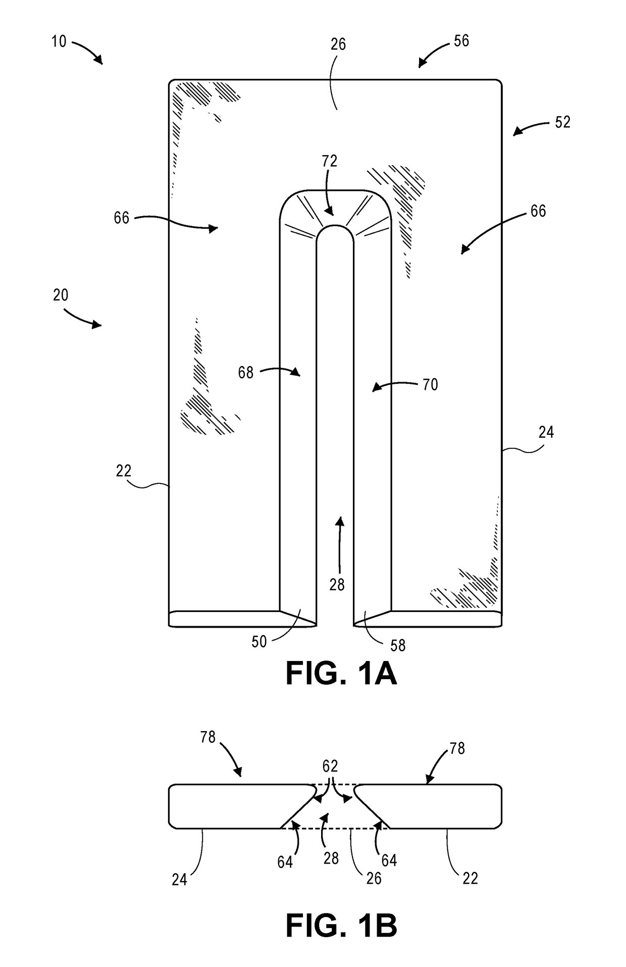
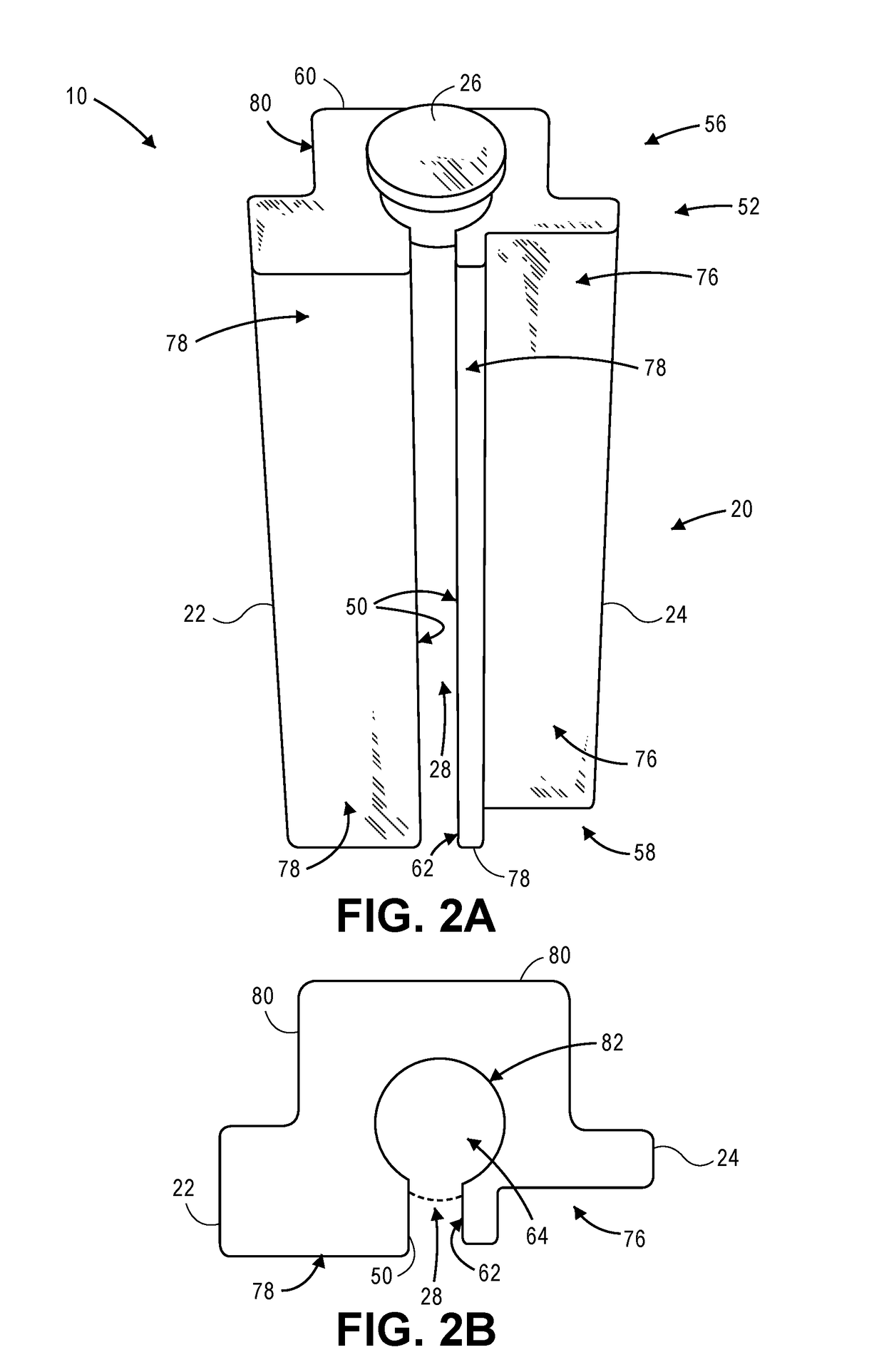
[0006]A first embodiment of the invention is broadly directed to a static hinge disabler for preventing the operation of a door hinge, comprising a first sidewall, a second sidewall, a channel, and a cap. The first sidewall is substantially parallel to the second sidewall. The channel is disposed between the first sidewall and the second sidewall and configured to receive at least a portion of the door hinge therein. The first sidewall and the second sidewall are statically connected such that the channel does not change shape. The first sidewall and the second sidewall therefore prevent the door hinge from operating while the door hinge is disposed within the channel. The cap is configured to keep the first sidewall and the second sidewall in contact with the door hinge. The channel presents a cap side that is proximate to the cap and an open side that is opposite the cap side. The channel is configured to receive the hinge from the open side.

Problems solved by technology

First, a malfeasant is often able to overcome the lock by applying a large force to the lock.
Second, the malfeasant is often able to overcome the lock by ‘picking’ or otherwise maliciously disengaging the lock.
Fourth, door locks cannot be used until they are properly (and typically permanently) installed onto the door and / or the wall.
Finally, these door locks of the prior art take time to secure and have moving components prone to failure.
Second, the static hinge disabler precludes any picking or disengagement from outside the door by moving the locking mechanism to a position in which it cannot be accessed by a malfeasant outside the door.
Third, when emplaced over a top hinge of a door, the static hinge disabler is out of the reach of children to prevent undesirable operation of the door.
A person need only slide the static hinge disabler over a door hinge to prevent that door from opening, which can save lives in a dangerous situation.

Method used


Image

  • Static hinge disabler
  • Static hinge disabler
  • Static hinge disabler

Examples


Embodiment Construction

[0027]The following detailed description references the accompanying drawings that illustrate specific embodiments in which the invention can be practiced. The embodiments are intended to describe aspects of the invention in sufficient detail to enable those skilled in the art to practice the invention. Other embodiments can be utilized and changes can be made without departing from the scope of the invention. The following detailed description is, therefore, not to be taken in a limiting sense. The scope of the invention is defined only by the appended claims, along with the full scope of equivalents to which such claims are entitled.

[0028]In this description, references to “one embodiment,”“an embodiment,” or “embodiments” mean that the feature or features being referred to are included in at least one embodiment of the technology. Separate references to “one embodiment,”“an embodiment,” or “embodiments” in this description do not necessarily refer to the same embodiment and are a...


PUM


Abstract

A static hinge disabler is provided for preventing the operation of a door hinge. The static hinge disabler includes a first sidewall, a second sidewall, a channel, and a cap. The first sidewall is substantially parallel to the second sidewall. The channel is disposed between the first sidewall and the second sidewall and configured to receive at least a portion of the door hinge therein. The first sidewall and the second sidewall are statically connected such that the channel does not change shape. The first sidewall and the second sidewall therefore prevent the door hinge from operating while the door hinge is disposed within the channel.

Description

RELATED APPLICATIONS[0001]This non-provisional patent application claims priority benefit, with regard to all common subject matter, of earlier-filed U.S. Provisional Patent Application No. 62 / 157,102, filed on May 5, 2015, and entitled “UNITARY DOOR HINGE LOCK.” The identified earlier-filed provisional patent application is hereby incorporated by reference in its entirety into the present application.BACKGROUND1. Field[0002]Embodiments of the invention are broadly directed to door locks. More specifically, embodiments of the invention are directed to disabling a door hinge to prevent the door from opening.2. Related Art[0003]Door locks come in a wide variety of apparatuses. Most door locks operate on an engaging portion of the door instead of a hinged portion of the door. These door locks secure the door to an adjacent portion of a wall via a locking mechanism. These locks are typically permanently installed on or near the door, so as to allow a user to prevent the door from operat...

Claims


Application Information

Patent Timeline
Patent Type & Authority Patents(United States)
IPC IPC(8): E05D11/10E05D3/02E05F5/02
CPCE05D11/1007E05D3/02E05F5/02E05D11/1014E05Y2900/132E05Y2201/22
Inventor POWELL, MICHAEL A.
Owner WASAWEGAN ENTERPRISES LLC
Why Eureka
Eureka Blog
Learn More