Fuel cell

a fuel cell and a technology of fuel cells, applied in the field of fuel cells, can solve the problems of inefficiency, inability to achieve desired sealing performance, and inability to efficiently perform assembling operation of fuel cells, etc., and achieve the effect of convenient and efficient assembling operation, simple structure and convenient stacked in alignment with each other

Inactive Publication Date: 2009-05-21
HONDA MOTOR CO LTD
View PDF11 Cites 5 Cited by
  • Summary
  • Abstract
  • Description
  • Claims
  • Application Information

AI Technical Summary

Benefits of technology

[0014]A main object of the present invention is to provide a fuel cell having a simple structure, in which separators can be stacked in alignment with each other easily and efficiently, and assembling operation of the fuel cell can be carried out efficiently.
[0016]The first and second separators are accurately positioned with the simple and quick operation. The first and second separators are electrically insulated from each other. Even if a large number of the fuel cells are stacked together, no positional displacement occurs between the fuel cells. The fuel cells are stacked together highly accurately. Thus, the desired sealing performance can be maintained.
[0017]According to the present invention, the second insulating positioning member is inserted into the first insulating positioning member for positioning the first and second separators to assemble the fuel cell. Then, a recess of the second insulating positioning member of the fuel cell is fitted to a protrusion of the second insulating positioning member of the adjacent fuel cell. In this manner, the fuel cells are simply stacked in alignment with each other. Thus, the fuel cell stack can be assembled efficiently.

Problems solved by technology

However, if the number of the fuel cells is large, it is difficult to insert the knock pins in the positioning holes, and assembling operation may not be performed efficiently.
Positional displacement between components may occur undesirably, and the desired sealing performance may not be achieved.
Thus, when a large number of unit cells 2 are stacked together, assembling operation of the fuel cell 1 is considerably laborious, and can not be performed efficiently.

Method used


Image

  • Fuel cell
  • Fuel cell
  • Fuel cell

Examples


first embodiment

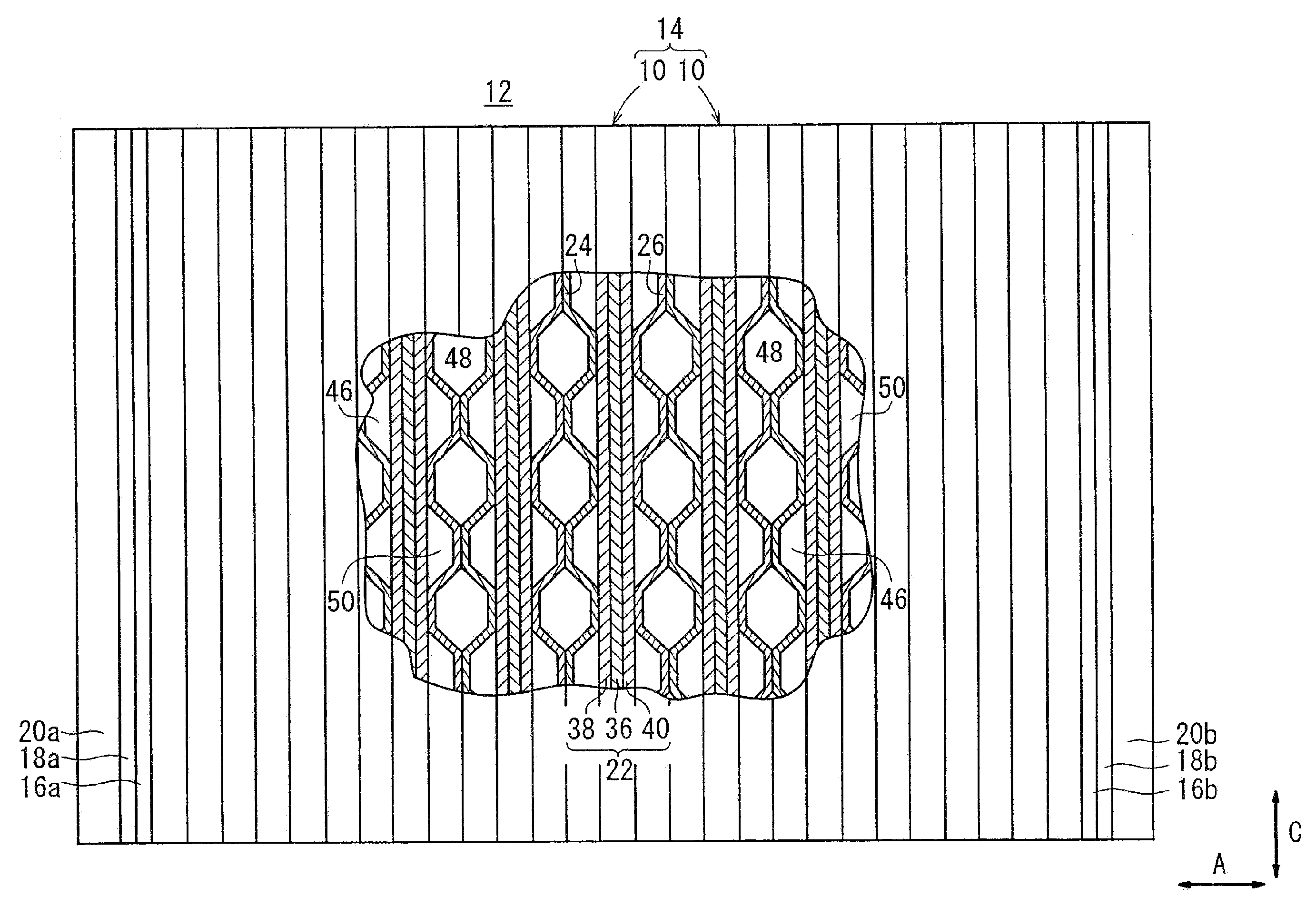
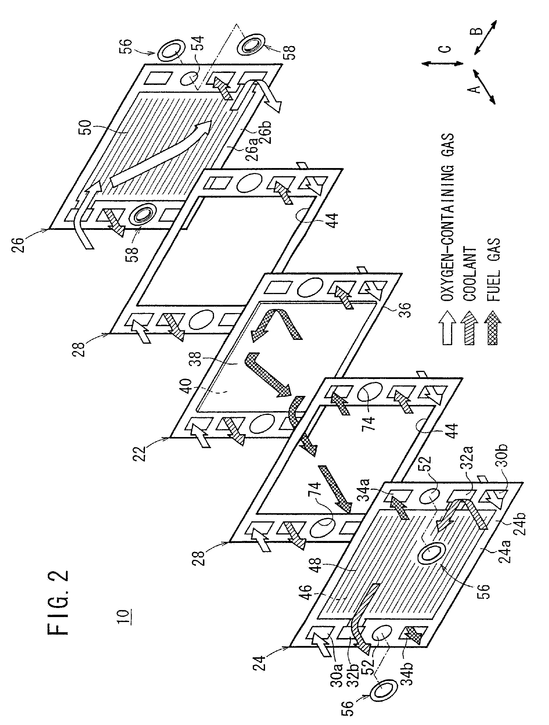
[0031]FIG. 1 is a view schematically showing a fuel cell stack 12 including fuel cells 10 according to the present invention.

[0032]The fuel cell stack 12 includes a cell assembly 14 formed by stacking a plurality of the fuel cells 10 in a stacking direction indicated by an arrow A. Terminal plates 16a, 16b are provided at opposite ends of the cell assembly 14 in the stacking direction indicated by the arrow A. Insulating plates 18a, 18b are stacked on the outside of the terminal plates 16a, 16b, respectively. Further, end plates 20a, 20b are stacked on the outside of the insulating plates 18a, 18b, respectively. The cell assembly 14, the terminal plates 16a, 16b, the insulating plates 18a, 18b, and the end plates 20a, 20b are tightened together by applying a predetermined tightening force to the end plates 20a, 20b.

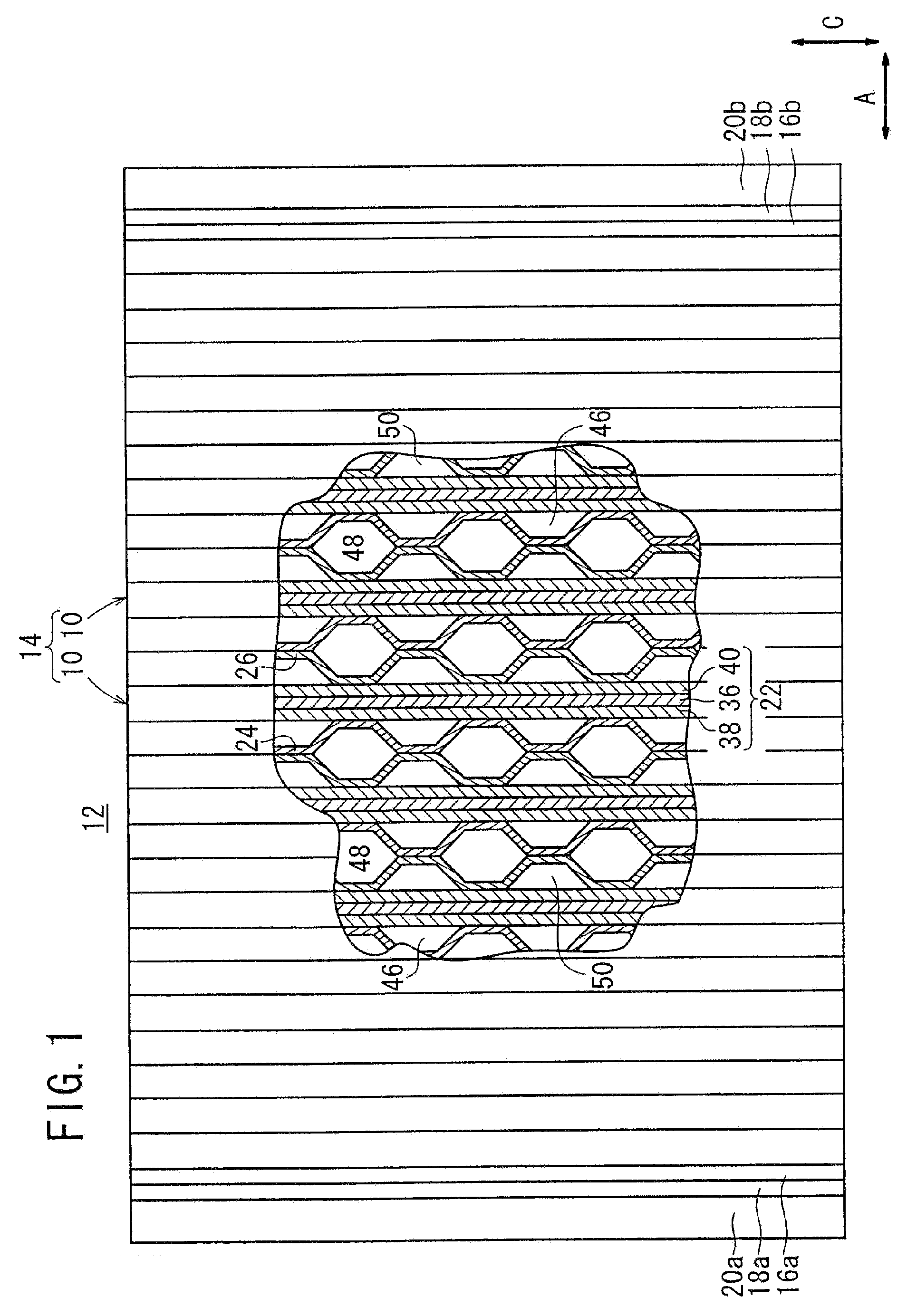
[0033]As shown in FIG. 2, the fuel cell 10 includes a membrane electrode assembly (electrolyte electrode assembly) 22 and first and second separators 24, 26 for sandwich...

second embodiment

[0059]In the second embodiment, no knock pins 80 are used for positioning the fuel cells 90 in alignment with each other. The recess 96 of the second insulating bushing 94 of one fuel cell 90 is fitted to the protrusion 98 of the second insulating bushing 94 of the adjacent fuel cell 90 for positioning the second insulating bushings 94 when these fuel cells 90 are stacked together.

[0060]The fuel cells 90 each having the second insulating bushing 94 are suitably positioned, and stacked together in the direction indicated by the arrow A to form the desired fuel cell stack 92. Assembling operation of the fuel cell stack 92 can be carried out rapidly and efficiently. Sealing performance of the fuel cell stack 92 is not degraded due to positional displacement between the fuel cells 90.

[0061]FIG. 6 is an enlarged cross sectional view showing a fuel cell stack 102 including fuel cells 100 according to a third embodiment of the present invention. FIG. 7 is an exploded perspective view showi...

third embodiment

[0063]In the third embodiment, the axial length of the outer wall 70 fitted to the inner wall 62 of the first insulating bushing 56 is increased by a distance H (see FIG. 6). The dimension of the contact area between the inner wall 62 and the outer wall 70 is increased by the distance H. Thus, the first insulating bushing 56 and the second insulating bushing 104 can be positioned more accurately.


PUM

PropertyMeasurementUnit
insulatingaaaaaaaaaa
chemicalaaaaaaaaaa
DC electric currentaaaaaaaaaa

Abstract

A fuel cell includes a membrane electrode assembly, and first and second separators. A first insulating bushing is attached to a first positioning hole of a first separator, and a second insulating bushing is attached to a second positioning hole of the second separator. An inner wall of the first insulating bushing is fitted to an outer wall of the second insulating bushing for positioning the first and second separators such that the first and second separators are insulated from each other.

Description

RELATED APPLICATIONS[0001]This application is a divisional of U.S. patent application Ser. No. 10 / 704,227 filed on Nov. 6, 2003 which claims priority to Japanese Patent Application No. 2003-350541, filed on Oct. 9, 2003 and Japanese Patent Application No. 2002-323950, Nov. 7, 2002, the contents of which are incorporated into this application in their entirety.BACKGROUND OF THE INVENTION[0002]1. Field of the Invention[0003]The present invention relates to a fuel cell including an electrolyte electrode assembly, and first and second separators for sandwiching the electrolyte electrode assembly. The electrolyte electrode assembly includes a pair of electrodes and an electrolyte interposed between the electrodes.[0004]2. Description of the Related Art[0005]For example, a solid polymer electrolyte fuel cell employs a membrane electrode assembly (MEA) which comprises two electrodes (anode and cathode) and an electrolyte membrane interposed between the electrodes. The electrolyte membrane ...

Claims


Application Information

Patent Timeline
Patent Type & Authority Applications(United States)
IPC IPC(8): H01M2/14H01M8/10H01M2/08H01M2/18H01M8/02H01M8/24
CPCH01M8/0247H01M8/0267H01M8/0273Y02E60/50H01M8/2465H01M8/248H01M2008/1095H01M8/241H01M8/242H01M8/2404H01M8/2457H01M8/2483H01M8/0297
Inventor GOTO, SHUHEIKOHYAMA, KATSUHIKOTAKAHASHI, KENFUJIWARA, SOSUZUKI, RYUGOSUGITA, NARUTOSHI
Owner HONDA MOTOR CO LTD
Why Eureka
Try Eureka