Panel

a panel and panel technology, applied in the field of panels, can solve problems such as relative brittleness, and achieve the effect of stable and reliable joint structur

Active Publication Date: 2018-06-12
UNILIN NORDIC AB
View PDF86 Cites 5 Cited by
  • Summary
  • Abstract
  • Description
  • Claims
  • Application Information

AI Technical Summary

Benefits of technology

[0028]Each of the first three features, in combination with the fact that the second point of contact is located at a higher position than the first point of contact, offers the advantage that any tendency according to which the downward projecting locking part might leave the female part, in particular due to a slight rotation, is counteracted. The fourth feature allows a smooth joining by the curved surfaces, whereas by the flat but inclined surfaces simultaneously a reliable locking is guaranteed.
[0032]According to still another preferred feature, the panel is characterized in that the second point of contact is located higher than the level that generally is defined by the lower side of said first laterally projecting lip. As a result a better resistance is offered against tearing off of material parts, such as the tearing off of locking portions.
[0034]According to still another preferred feature, the panel is characterized in that, seen in cross section, said first joint profile comprises only one vertically active locking portion at each side of said male part. This assists in a smooth joining.
[0036]In the most preferred embodiment, the downward projecting locking part of the first joint profile is a solid part, at least in between the first and second points of contact. This offers the advantage that a stable material part is present between the points of contact, resulting in that no unwanted compression may occur.
[0044]Preferably, said first joint profile and said second joint profile are cut profiles, resulting in that an easy manufacturing is possible, for example, by milling cutters that are positioned under appropriate angles in respect to the plane of the panels and / or by scrapers and / or any other tools.
[0047]Preferably, the panels according to the invention comprise a wood-based core or wood-based core layer. The aforementioned joint profiles, due to the claimed features, are of an utmost appropriate configuration for the integration in wood-based panels, as the claimed configuration provides an optimum compromise between good joining features and a stable and reliable joint structure.

Problems solved by technology

As is well known, such fiberboard is a very economical material for the production of covering panels, such as decorative floor panels, however, shows the disadvantage that it is relatively brittle.

Method used


Image

  • Panel
  • Panel
  • Panel

Examples


Embodiment Construction

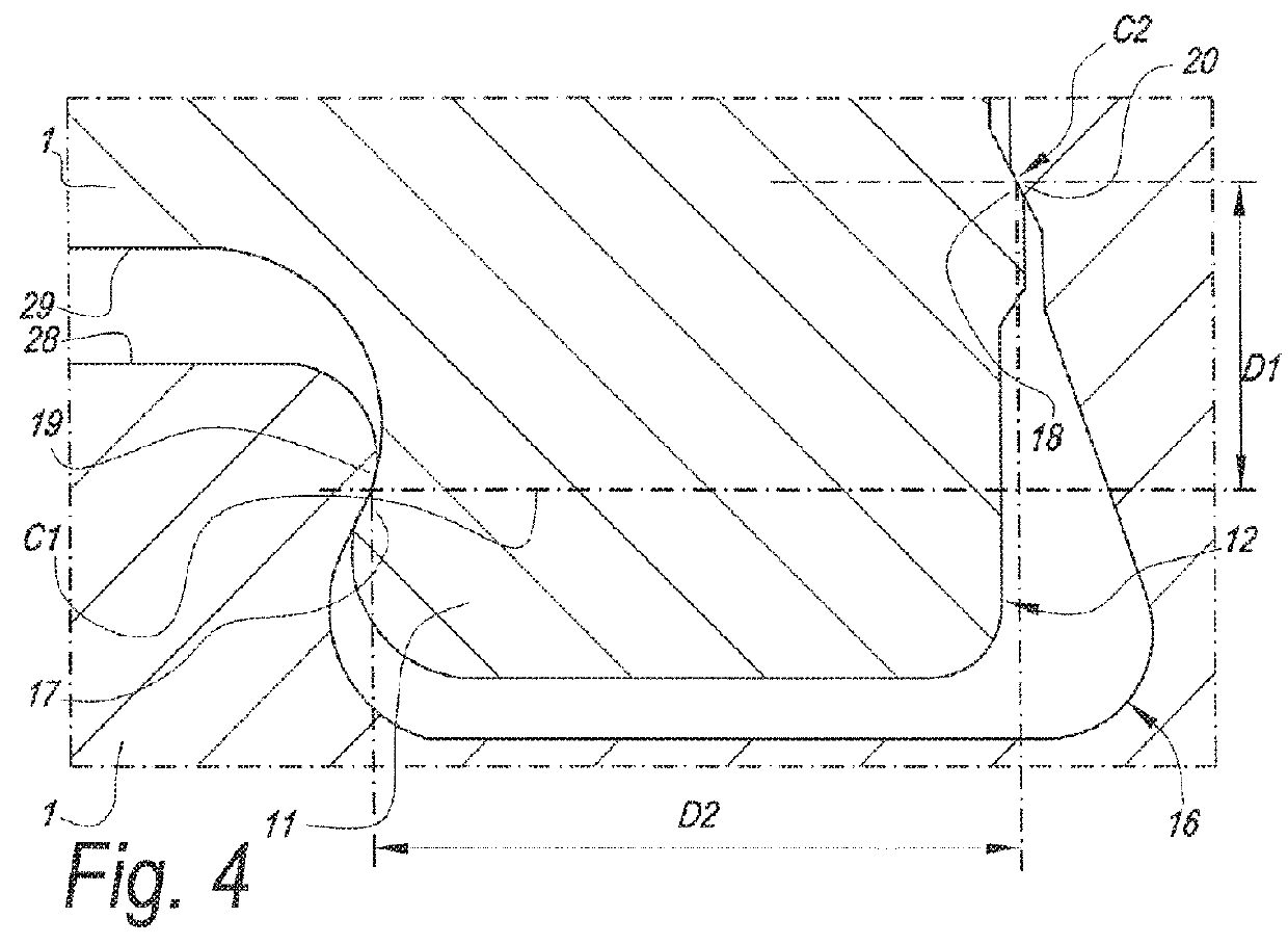
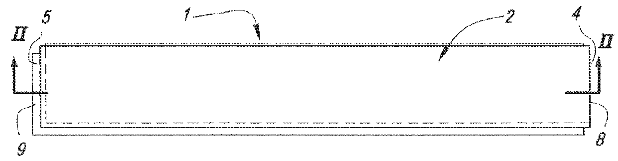
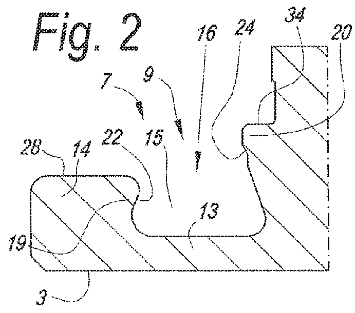
[0058]As represented in the drawings, the present invention relates to a panel 1 having an upper surface 2, a lower surface 3 and at least one pair of opposite edges 4-5;[0059]wherein said pair of edges 4-5 comprises a first edge 4 having a first joint profile 6 and a second edge 5 having a second joint profile 7;[0060]wherein said joint profiles 6-7 define coupling parts 8-9 allowing that two of such panels 1 can be joined or are joinable by a downward movement M of the edge of one panel 1 in respect to the edge of the other panel 1, wherein said coupling parts 8-9 in a coupled condition provide a locking in a direction R1 perpendicular to the plane of the coupled panels 1, as well as in a direction R2 parallel to the plane of the coupled panels 1 and perpendicular to the respective edges 4-5;[0061]wherein the first joint profile 6 comprises a first laterally projecting lip 10 with a downward projecting locking part 11, said downward projecting locking part 11 defining a male part ...


PUM

PropertyMeasurementUnit
timeaaaaaaaaaa
thermoplasticaaaaaaaaaa
thicknessaaaaaaaaaa

Abstract

A panel, which, at two opposite edges, is provided with coupling parts that allow joining by a downward movement, said coupling parts including a male part that fits in a female part, wherein vertically active locking portions are provided at opposite sides of the male part and female part, wherein these locking portions are located at different distances from an upper side of the panels.

Description

CROSS-REFERENCE TO RELATED APPLICATIONS[0001]This application is a continuation of and claims priority to U.S. patent application Ser. No. 14 / 633,923, filed Feb. 27, 2015, which is a continuation of and claims priority to PCT Patent Application No. PCT / IB2013 / 058022 filed Aug. 27, 2013, which claims the benefit of and priority to U.S. Provisional Patent Application No. 61 / 693,668, filed Aug. 27, 2012, the entire disclosures of which are incorporated by reference herein.BACKGROUND[0002]1. Technical Field[0003]The present invention relates to a panel. In first instance, it relates to a floor panel, however, more generally, the invention can also be applied in other types of panels, for example, panels for a wall covering or ceiling.[0004]More specifically, the invention relates to panels which on their edges can be coupled to each other and interlocked.[0005]In particular, the invention relates to a panel of the type having an upper surface, a lower surface and at least one pair of op...

Claims


Application Information

Patent Timeline
Patent Type & Authority Patents(United States)
IPC IPC(8): E04F15/02E04F15/04E04F15/10
CPCE04F15/02038E04F15/105E04F2201/0146E04F2201/043E04F2201/023E04F2201/042E04F2201/0153F16B5/0056E04F2201/03E04F15/045E04F15/107E04F2201/0138
Inventor STEVENS, JR., CHARLES EDWARD
Owner UNILIN NORDIC AB
Why Eureka
Try Eureka