Antenna connector

A connector and antenna technology, applied in the directions of antennas, folded antennas, antenna parts, etc., can solve the problem that the antenna 2 cannot be returned and snapped into place.

Inactive Publication Date: 2008-06-11
GALTRONICS OPTICAL LTD
View PDF5 Cites 0 Cited by
  • Summary
  • Abstract
  • Description
  • Claims
  • Application Information

AI Technical Summary

Problems solved by technology

If the arm 6 is damaged, the antenna 2 will not snap back into place and the consumer may return the mobile phone for repair

Method used


Image

  • Antenna connector
  • Antenna connector
  • Antenna connector

Examples


Embodiment Construction

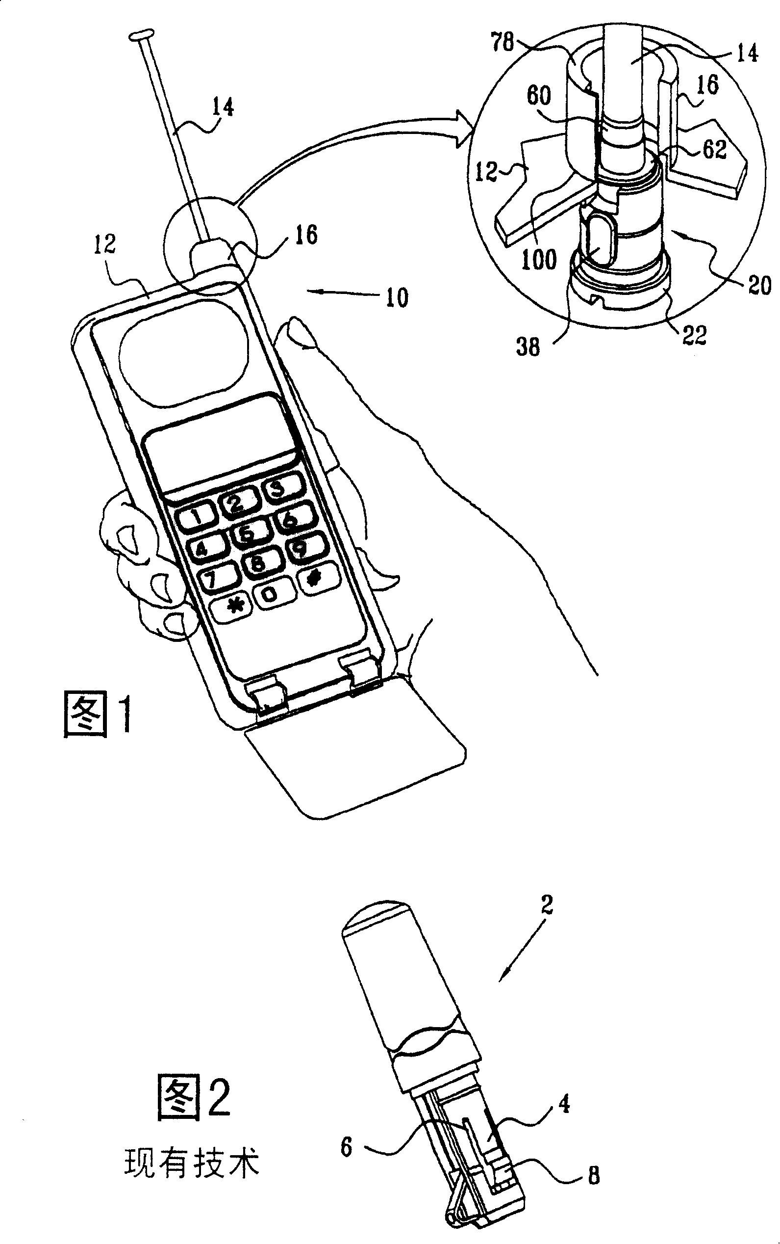
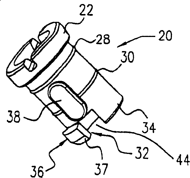
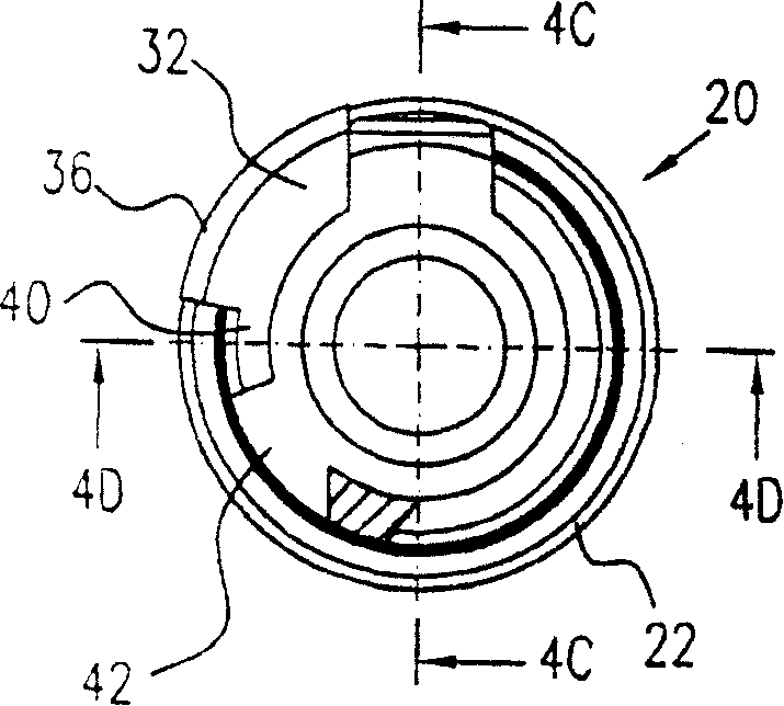
[0040] Referring first to FIG. 1, this figure is a schematic diagram showing a mobile phone according to a first preferred embodiment of the present invention. In the embodiment of FIG. 1, the mobile telephone 10 includes a housing 12 through which an antenna 14 is insertable. The antenna 14 has a socket 16 through which a image 3 The described connector 20 plugs into the antenna. Connector 20 snaps into place in receptacle 16 and functions to securely secure antenna 14 to housing 12, preferably in a manner that resists accidental separation due to longitudinal or shear forces. As described below, in one embodiment, the connector is capable of securing itself in place within the housing until a prescribed level of longitudinal force is reached. If this specified level is exceeded, the connector is free to disengage. In another embodiment, a key may be used to rotate the connector to disengage from the housing 12 .

[0041] Referring to Fig. 2, this figure is a simplified d...


PUM


Abstract

A connection mechanism for snap-fitting an antenna (14) into a hole in a receptacle (16), the receptacle (16) typically being part of a 2-way mobile communication device. A latch (4), preferably mounted on a sleeve, including a stem and a latch head (8), extends around a circumference of the antenna (14). The latch (4) is inwardly depressible to insert the antenna through the hole and is able to return to a non-depressed position to retain the antenna against the second end.

Description

technical field [0001] The present invention relates to antenna connectors, in particular but not exclusively to antenna connectors for snap-fitting within housings. Background technique [0002] Devices requiring antennas include one-way and two-way radiotelephones and mobile phones. This type of device includes a housing, and usually requires the antenna to be electrically connected to the internal circuit through the housing, and mechanically firmly fixed on the housing so that the antenna will not be accidentally detached due to longitudinal or tangential force. In addition, it is desirable that the antenna be relatively easy to remove intentionally. [0003] In Fig. 2 a conventional mobile phone and a typical prior art antenna are shown. The stubby antenna 2 has a snap-fit ​​connection comprising a snap (latch) 4 at its lower end to enable it to be pressed into the housing 12 of the mobile phone 10 . The latch 4 includes an arm 6 and a latch head 8 . When the antenn...

Claims


Application Information

Patent Timeline
IPC IPC(8): H01Q1/24H01Q1/36H01Q1/08H01Q1/10
CPCH01Q1/103H01Q1/36H01Q1/243H01Q1/088H01Q1/24
Inventor 费利克斯·普鲁斯鲁维姆·戈尔德曼
Owner GALTRONICS OPTICAL LTD
Why Eureka
Try Eureka